Low Power Outdoor (LPOD) Amplifier/Block Up Converter (BUC)
Revision 15
Introduction 1–7 MN-LPOD
1.4.6 Block Up Converter (BUC) Input
The LPOD translates an L-Band input carrier to the desired output frequency (C-, X-, or
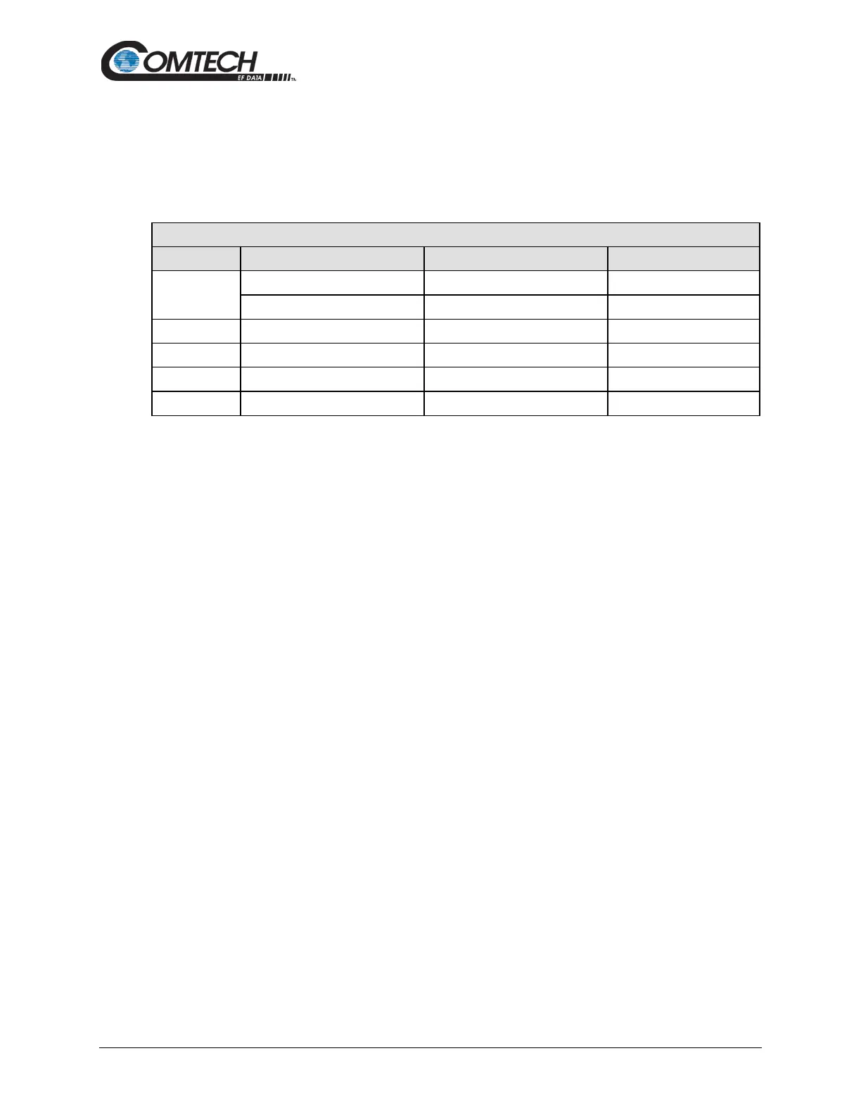
Ku-Band). Local Oscillator (LO) frequencies are as follows:
Table 1-1. Low Oscillator (LO) Frequencies
BUC C, Ku, X LO Frequencies
C-Band
Unlike most BUCs, no DC bias voltage should be provided on the center conductor of the L-Band
coax. In addition, the LPOD is available with an internal 10 MHz reference. As such, no 10 MHz
reference is required on the center conductor of the L-band coax. If a reference is provided on the
coax, the internal reference will detect and lock to it.
1.4.7 Monitor and Control (M&C)
The LPOD includes a microprocessor-based system that provides monitoring and control of the
essential parameters of the unit. The user interfaces with the unit through the M&C system via the
remote control/discrete communications port.
The unit is capable of EIA-232, EIA-485, or Ethernet remote communication. A discrete mute
control and relay status output is also available.
The M&C system monitors the fan speed (PS 2 only), unit temperature, all power supply voltages,
power transistor currents, output power, etc. Should a critical monitored parameter fail, the unit
will mute the RF signal and report a fault. The details of the fault can be accessed via remote
communication.
The M&C is also capable of acting as a controller in a 1:1 redundant system. When configured as
the back-up SSPA in such a system, it communicates with the other SSPA and toggles the
waveguide switches as necessary.