Low Power Outdoor (LPOD) Amplifier/Block Up Converter (BUC)
Revision 15
Appendix A A–12 MN-LPOD
A.4 1:1 Redundancy System Assembly Kit Examples
Chapter 2. SYSTEM CONNECTORS, INSTALLATION,
AND STARTUP
The illustrations provided in this appendix are intended as reference examples only. The dimensions shown in these
example figures are subject to change and may not reflect your installed configuration.
Several kits are available from CEFD to mount and install standalone or redundant LPODs, depending on the type of unit ordered and its
operational frequency.
The figures and tables provided in the subsections that follow illustrate the CEFD kits currently available for assembling LPOD PS 1, PS 1.5
or PS 2 1:1 Redundancy Systems. Unless otherwise noted, all 1:1 Redundancy Kit figures depict use of AC Option, Waveguide Output
LPODs. Refer to Chapter 2. SYSTEM CONNECTORS, INSTALLATION
AND STARTUP for the available assembly kit options for LPOD
Standalone configurations.
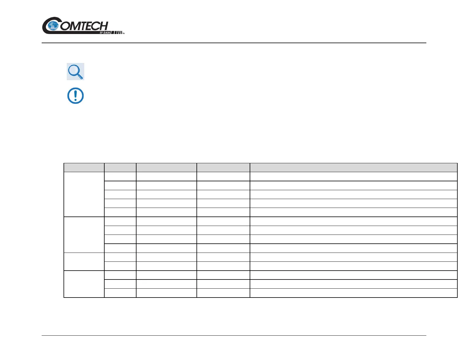
A.4.1
Common Kits
FREE STANDING 1:1 UNISTRUT KIT
Rx SWITCH, LPOD C-BAND KIT
Rx SWITCH, LPOD Ku-BAND KIT
Rx SWITCH, Ku-BAND, METRIC KIT
A.4.2
LPOD PS 1
PS 1 C-BAND 1:1 KIT, MTG & CABLE, Tx SWITCH
PS 1 C-BAND COAX OUTPUT1:1 KIT, MTG & CABLE, Tx SWITCH
PS 1 Ku-BAND 1:1 KIT, MTG & CABLE, Tx SWITCH
PS 1 X-BAND 1:1 KIT, MTG & CABLE, Tx SWITCH
A.4.3
LPOD PS 1.5
PS 1.5 C-BAND DC OPTION 1:1 KIT, MTG & CABLE, Tx SWITCH
PS 1.5 Ku-BAND 1:1 KIT, MTG & CABLE, Tx SWITCH
A.4.4
LPOD PS 2
PS 2 C-BAND 1:1 FREE STANDING MOUNTING KIT
PS 2 C-BAND 1:1 KIT, MTG & CABLE, Tx SWITCH
PS 2 Ku-BAND 1:1 KIT, MTG & CABLE, Tx SWITCH