Home
Comtech EF Data
Amplifier
HPOD
Comtech EF Data HPOD - User Manual
156 pages
Manual
Specs
Ask a question
Save Page as PDF
To Next Page
To Next Page
Loading...
Part Number MN/HPOD.IOM Revis
ion 6
IMPORTANT NOTE: Th
e information contain
ed in this document supe
rsedes all previo
usly published
information regarding th
ese products. Product sp
ecific
atio
ns are subject to change withou
t prior notice.
HPOD
C-, X-, Ku-Band High-Power Outdoor Amplifier
Installation and Operation Manual
2
Table of Contents
Main Page
Default Chapter
11
Installation and Operation Manual
11
Table of Contents
13
Table of Contents
14
Table of Contents MN/HPOD.IOM
18
Preface
19
About this Manual
19
Disclaimer
19
Conventions and References
19
Patents and Trademarks
19
Warnings, Cautions, and Notes
19
Examples of Multi-Hazard Notices
20
Recommended Standard Designations
20
Metric Conversion
20
Electrical Safety Notice
20
Installation Guidelines Regarding Power Line Quality
21
Warranty Policy
22
Limitations of Warranty
22
Exclusive Remedies
23
Getting Help
24
Contacting Comtech EF Data
24
Returning a Product for Upgrade or Repair
25
Chapter 1. INTRODUCTION
27
Overview
27
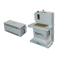
Figure 1-1. Comtech EF Data HPOD SSPA
27
Features
28
Functional Description
28
Dimensional Envelope
29
Figure 1-2. HPOD SSPA Dimensional Envelope
29
Theory of Operation
30
Figure 1-3. Comtech EF Data HPOD SSPA Block Diagram
30
SSPA Module
31
Power Supply
31
Cooling System
31
Monitor and Control (M&C)
31
Block up Converter Input Option
32
Specifications
33
Chapter 2. EXTERNAL CONNECTORS and PINOUTS
35
Cabling Connection Types
35
Coaxial Cable Connections
35
Circular Cable Connections
35
Figure 2-1. Coaxial Connector Example
35
HPOD SSPA Cabling Connections
36
Figure 2-2. Circular Connector Example
36
Table 2-1. HPOD SSPA External Connectors
37
Figure 2-3. HPOD External Connectors
37
RF Signal Interface Connector Group
38
J1 | RF in Connector
38
J2 | RF out Connector
38
Table 2-2. J2 | RF out Waveguide Output Flange
38
Ground and Power Connection Group
39
Ground Connection
39
J3 | AC in Connector (AC Power Main)
39
Table 2-3. J3 | AC in Connector Pinout
39
J10 Connector: Optional -48V DC Power Supply
40
Table 2-4. J10 Connector Pinout
40
Electrical Control Interface Connection Group
41
J4 | REDUNDANT LOOP Connector
41
Table 2-5. J4 | REDUNDANT LOOP Connector Pinout
41
J6 | COM1 Connector
42
J8 | INPUT SAMPLE Connector
42
J9 | OUTPUT SAMPLE Connector
42
Table 2-6. J6 | COM1 Connector Pinout
42
Energizing the HPOD SSPA
43
Figure 2-4. HPOD Unit
43
Chapter 3. UPDATING FIRMWARE
45
Introduction
45
Getting Started: Preparing for the Firmware Download
46
Downloading and Extracting the Firmware Update
49
Performing the FTP Upload Procedures
52
Performing the Automated Serial-Based FTP Upload Procedure
52
Performing the Ethernet-Based FTP Upload Procedure
54
Chapter 4. Ethernet-Based Remote Product Management
58
Ethernet Management Interface Protocols
58
SNMP Interface
58
Management Information Base (MIB) Files
58
SNMP Community Strings
59
SNMP Traps
59
Telnet Interface
60
Telnet Operation Via Hyperterminal
61
HPOD Web Server (HTTP) Interface
62
Enabling the Web Server Interface
62
User Login
64
Web Server Interface - Operational Features
65
Navigation
65
Page Sections
65
Action Buttons
65
Drop-Down Lists
65
Home | Home Page .................................................................................................. 4–11
65
Home | Contact Page . ............................................................................................... 4–12
65
Home | Support Page ............................................................................................... 4–13
65
Text or Data Entry
66
Web Server Interface - Menu Tree
66
Admin | Access Page . ................................................................................................ 4–14
66
Admin | SNMP Page . ................................................................................................. 4–16
66
Config | Amplifier Page . ............................................................................................ 4–17
66
Config | Utility Page . ................................................................................................. 4–19
66
Config | Redundancy Page . ....................................................................................... 4–20
66
Home Pages
67
Admin Pages
70
Config Pages
73
Date and Time
75
Status Pages
77
Chapter 5. SERIAL-BASED REMOTE PRODUCT MANAGEMENT
81
Overview
81
Key Operational Parameters
81
RF Input Level
81
Attenuator Control
82
Mute Control
82
Faults
82
Power Detector
83
Most Common Remote Queries
83
Serial Remote Control Introduction
83
Basic Protocol
84
Packet Structure
85
Start of Packet
86
Target Address
86
Address Delimiter
86
Instruction Code
86
Instruction Code Qualifier
86
Optional Message Arguments
88
End of Packet
88
Remote Commands and Queries
89
Appendix A. Redundancy System Assembly Kits
101
Introduction
101
Table A-1. Summary of Available Redundancy System Assembly Kits
102
Common Mounting Kits
104
Table A-2. Universal Pole Mounting Kit (CEFD P/N PL/12319-1) Parts List
104
Table A-3. HPOD Unit Mounting Kit (CEFD P/N PL/12300-1) Parts List
106
Table A-4. HPOD 1:1 Redundancy System - Common Unistrut Kit (CEFD P/N KT/12200-1) Parts List
108
Table A-5. HPOD 1:2 Redundancy System - Common Unistrut Kit (CEFD P/N KT-0000017) Parts List
110
1:1 Redundancy System Mounting and Switch Kits
112
Table A-6. ODPA C-Band 1:1 Redundancy Switch/Waveguide Kit (CEFD P/N KT/11799) Parts List
118
Table A-7. ODPA X-Band 1:1 Redundancy Switch/Waveguide Kit (CEFD P/N KT/11387-1) Parts List
120
Table A-8. HPOD C-Band 1:1 Redundancy Switch/Waveguide Kit (CEFD P/N KT/12201-1) Parts List
123
Table A-9. HPOD C-Band Offline Unit Termination Bypass Waveguide Kit (CEFD P/N KT-0020523) Parts List
125
Table A-10. Ku-Band 1:1 Redundancy Assembly Kit (CEFD P/N KT/11936-1) Parts List
127
Table A-11. HPOD Ku-Band 1:1 Redundancy Switch/Waveguide Kit (CEFD P/N KT/12337-1) Parts List
129
1:2 Redundancy System Mounting and Switch Kit Examples
132
Appendix B. 1:1 and 1:2 REDUNDANCY OPERATION
137
Introduction
137
B.1.1 1:1 Redundancy Mode
137
Redundancy Operation Using the HPOD Web Server Interface
141
B.2.1 HPOD Web Server Interface Overview
141
Redundancy Operation Using Serial-Based Remote Commands and Queries
144
HPOD Series 1:1 Redundancy Test
146
Appendix C. MAINTENANCE
149
Introduction
149
Replacing the Power Supply
150
C.2.1 Removing the Old Power Supply
150
C.2.2 Installing the New Power Supply
151
Replacing the Fan Assembly
152
C.3.1 Removing the Old Fan Assembly
152
C.3.2 Installing the New Fan Assembly
153
Scheduled Maintenance
154
Need help?
Do you have a question about the Comtech EF Data HPOD and is the answer not in the manual?
Ask a question
Comtech EF Data HPOD Specifications
General
Brand
Comtech EF Data
Model
HPOD
Category
Amplifier
Language
English
Related product manuals
Comtech EF Data LPOD
224 pages
Comtech EF Data LPOD PS 1.5
238 pages
Comtech EF Data LPOD Series
238 pages