HPOD C-, X-, Ku-Band High-Power Outdoor Amplifier Revision 6
External Connectors and Pinouts MN/HPOD.IOM
2–2
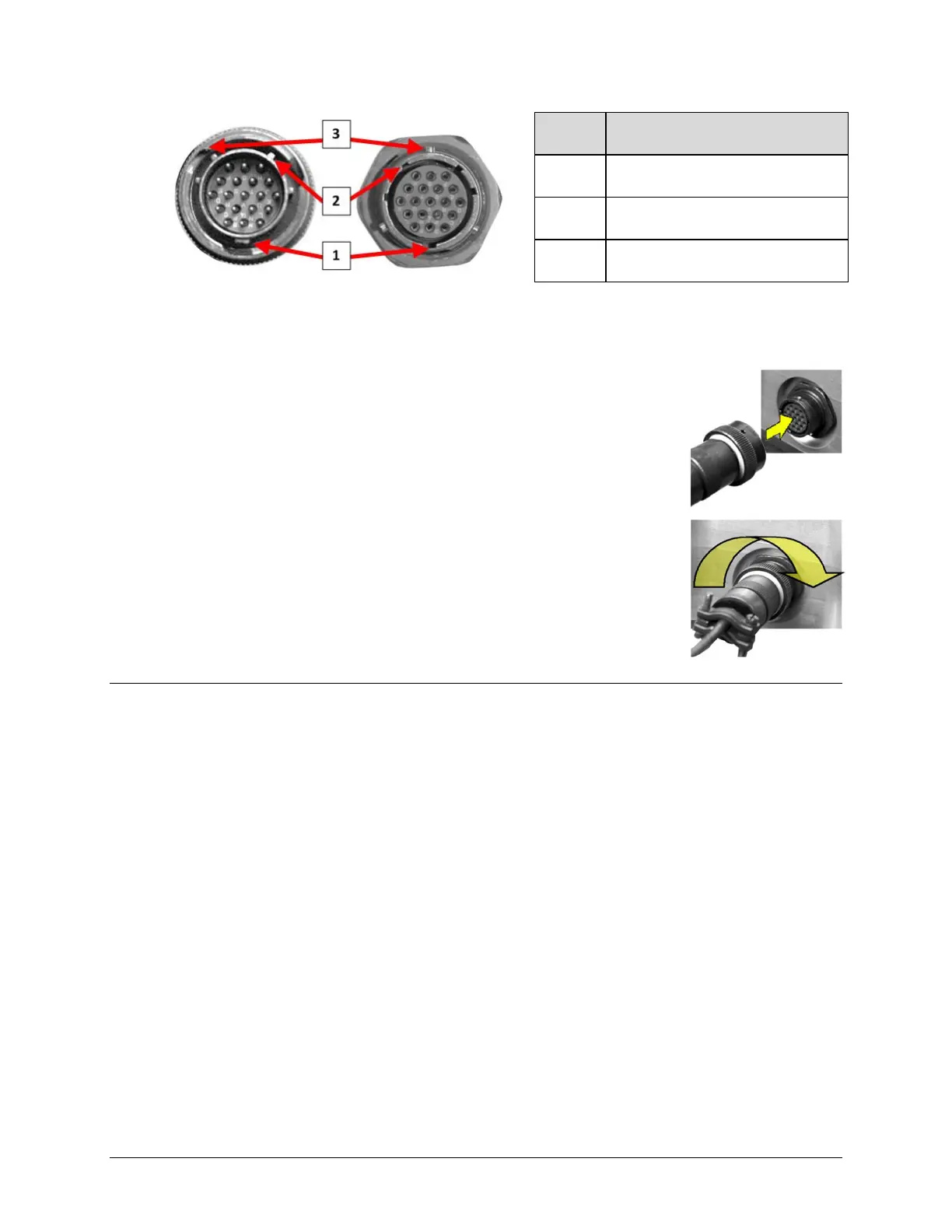
Feature Description
1 Primary Alignment features
2 Secondary Alignment features
3 Sleeve Lock features
Figure 2-2. Circular Connector Example
Connection Instructions – Engage all of the alignment and lock
features between the male connector (on the interconnection cable)
andfemalesocket.
Toinstallthemaleconnectorintothefemaleconnector:
1. Engage the primary and secondary alignment tabs on the male
connectorwiththematingcutoutsonthefe
malesocket.
2. Pushthemaleconnectorintothefemalesocket.
3. Turn the male connector sleeve clockwise until the sleeve lock
cutouts engage fully with the female socket tabs and you hear a
“click”sound
2.2 HPOD SSPA Cabling Connections
TheHPODSSPAexternalconnectors(Figure2‐3)provideallnecessaryconnectionsbetweenthe
unit and other equipment. Table 2‐1 summarizes the conne
ctors provided here, grouped
accordingtoservicefunction.
Additionally:
• Detailed installation and operational information for using HPODs in 1:1 and 1:2
redundancyconfigurationsisprovidedinAppendixA.REDUNDANCYSYSTEMASSEMBLY
KITSandAppendix B.1: 1
AND1:2REDUNDANCYOPERATION.
• Information on the HPOD’s M&C operability via serial remote commands and queries is
providedinCHAPTER5.SERIAL‐BASEDREMOTEPRODUCTMANAGEMENT.