135Condair CDA and CDA-S
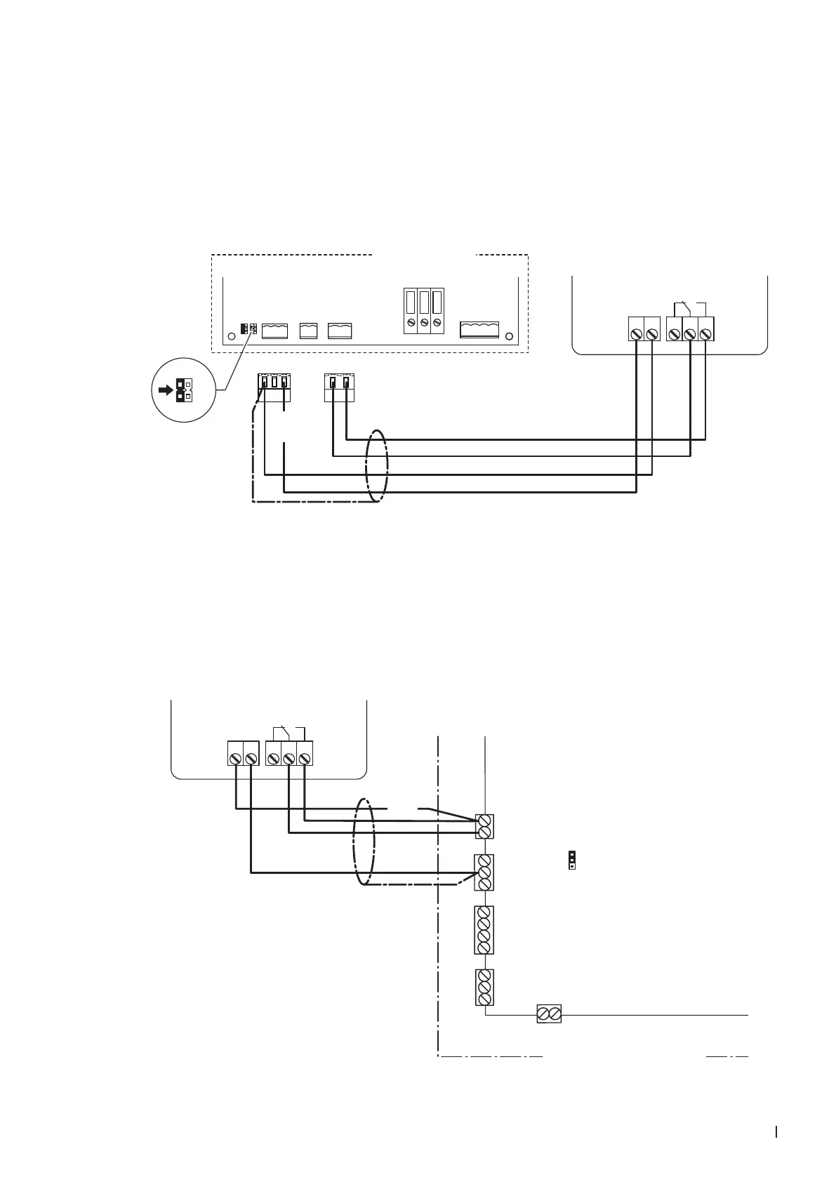
10.7.7 Connecting the CDA to the Condair CP3mini
1. Connect the Condair CDA to the corresponding terminals on the power board of the Condair CP3mini
according to the wiring diagram below.
Note: The voltage supply of the Condair CDA is established via the terminals "V+" and "GND" of
terminal block "X1" or via an external 24 V AC/DC voltage supply.
2. On the power board of the Condair CP3mini: set a Jumper on JP2-24 V and remove the Jumper on
JP1-5V (if a jumper is set).
CONT.SIGN
V+
GND CTRL
X1 X4 X6
CTRL V+
1 21 21 2 3
GND
BASIC
0-10V
On/Off
24V
5V
PRO
JP4
JP3
JP2
JP1
LIMGND SC1SC2
SAFETY
SC1SC2
24V
5V
JP2
JP1
Condair CP3 mini
PWR
MAIN SUPPLY
X9
L
N PE
X8
N L SW N SWL
12 11 141 2
L1 N
NC C NO
CDA
24 VDC
Power board Condair CP3mini
10.7.8 Connecting the CDA-S to the Condair MD
1. Connect the Condair CDA-S to the corresponding terminals on the driver board of the Condair MD
according to the wiring diagram below.
Note: The voltage supply of the Condair CDA-S is established via the terminals "24V" of terminal
block "X15" and "GND" of terminal block "X13" or via an external 24 V AC/DC voltage supply.
2. Set a jumper on JP4-24V on the driver board of the Condair MD.
X11
X10
X12
X13
JP4
X15
Hygro
24V+
Temp
Hum 1
Hum 2
10V/24V+
GND
GND
GND
GND
Leak
24V
24V
Safety
10V24V
12 11 141 2
L1 N
NC C NO
CDA-S
24 VDC
Driver board Condair MD
Hydraulic unit Condair MD