51Condair CRC and CRC-NA
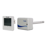
3.8.7 Connecting the CRC or CRC-NA am Condair CP3mini
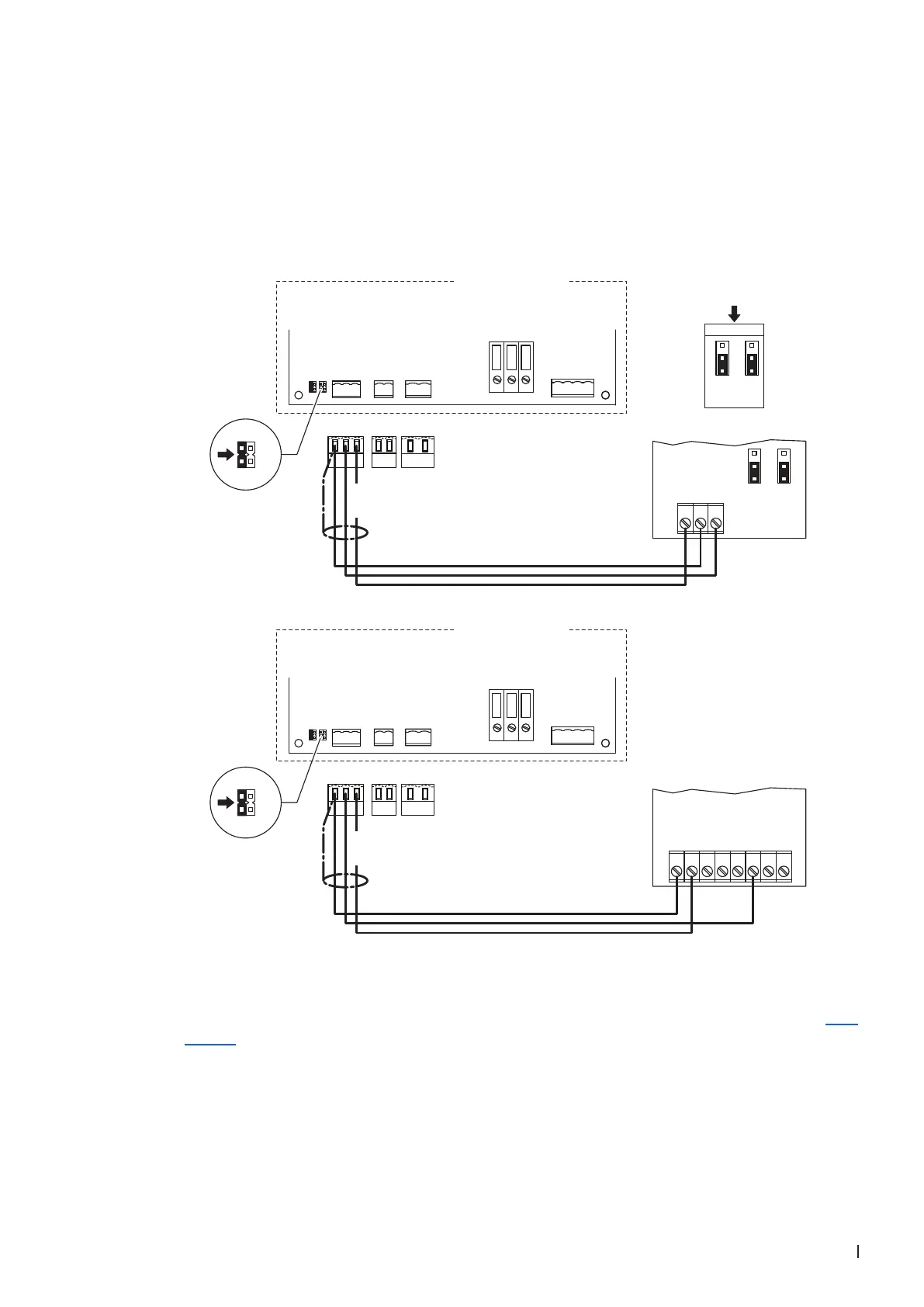
1. Connect the CRC to the corresponding terminals of terminal block "X1" on the power board of the
Condair CP3mini according to the appropriate wiring diagram (see below).
Note: The voltage supply of the CRC is established via the terminals "V+" and "GND" of terminal
block "X1" or via an external 24 V AC/DC voltage supply.
2. On the power board of the Condair CP3mini: set a Jumper on JP2-24 V and remove the Jumper on
JP1-5V (if a jumper is set).
CONT.SIGN LIM.SIGN
V+ LIMGND
GND CTRL
X1 X4 X6
CTRL V+
1 21 21 2 3
GND
BASIC
0-10V
On/Off
24V
5V
PRO
JP4
JP3
JP2
JP1
LIMGND SC1SC2
SAFETY
SC1SC2
24V
5V
JP2
JP1
Condair CP3 mini
PWR
MAIN SUPPLY
X9
L
N PE
X8
N L SW N SWL
***
0...10V
24V AC/DC
0V/GND
H OUT
JP1
2
3
1
JP3
2
3
1
***
1 2 3
JP1
2
3
1
JP3
2
3
1
24 VDC
CONT.SIGN LIM.SIGN
V+ LIMGND
GND CTRL
X1 X4 X6
CTRL V+
1 21 21 2 3
GND
BASIC
0-10V
On/Off
24V
5V
PRO
JP4
JP3
JP2
JP1
LIMGND SC1SC2
SAFETY
SC1SC2
24V
5V
JP2
JP1
Condair CP3 mini
PWR
MAIN SUPPLY
X9
L
N PE
X8
N L SW N SWL
24 VDC
24V AC/DC
0V/GND
A0 2-10V
1 2 3 4 5 6 7 8
Power board
Condair CP3mini
Power board
Condair CP3mini
CRC (Signal Y)
CRC-NA (Signal Y)
3. Only for CRC: Set the output signal of the CRC to "0-10V" using the Jumpers JP1 and JP3 on the
control board of the CRC.
Note: other output signal settings (e.g. 4-20mA) are also possible, see CRC jumper settings in Sec-
tion 3.7.