-
-
-
- 8 -
-
-
-
Method
Method
Method
Method to
to
to
to use
use
use
use the
the
the
the knob
knob
knob
knob to
to
to
to operate
operate
operate
operate on
on
on
on the
the
the
the screen:
screen:
screen:
screen:
The rectangular mark on the screen that moves with the rotation of the knob is called “ cursor ” .
Operation can be performed at any position at which the cursor can stay.
When the cursor is in the waveform area, the user may immediately modify the current setup. When the
cursor is in the parameter area, the user may open the setup menu of the corresponding parameter
module so as to set up the menu items of the module.
Operating method :
■ Move the cursor to the item where the operation is wanted
■ Press the knob
■ One of the following four situations may appear:
1. The cursor with yellow frame become s into the one with cyan frame , which implies that the content
in the frame can change with the rotation of the knob.
2. Menu or measuring window may appear on the screen, or the original menu is replaced by the new
menu.
3.
A
check mark “ √ ” appears at the position, indicating that the item is confirmed.
4. The system immediately executes a certain function.
1.4
1.4
1.4
1.4 Interfaces
Interfaces
Interfaces
Interfaces
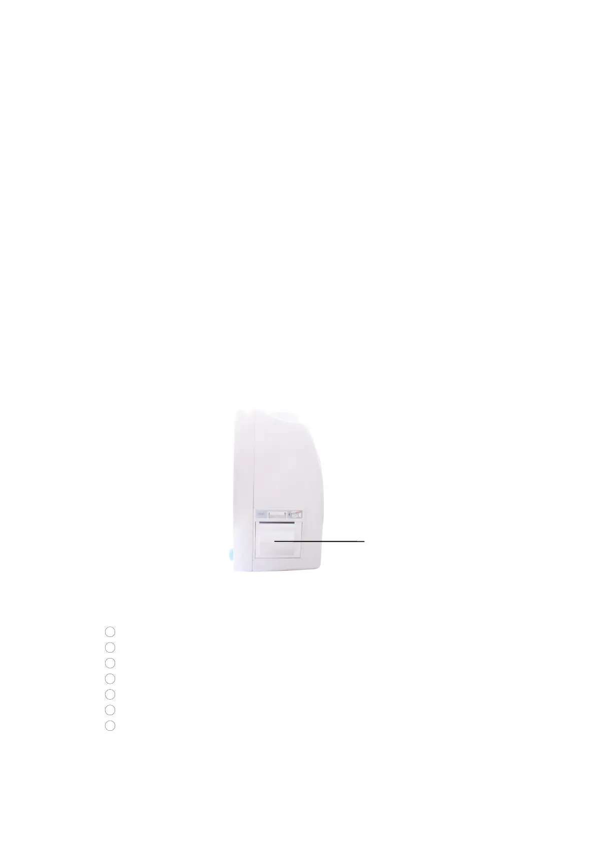
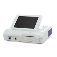
For the convenience of operation, the different kinds of interfaces are in different parts of the monitor.
At the right side is the recorder( Figure 1 -2)
①
Figure
Figure
Figure
Figure 1
1
1
1 -2
-2
-2
-2 Right
Right
Right
Right Side
Side
Side
Side
At the left side are the connectors to patient cables and the sensors, as shown in Figure 1-3.
1 Socket for CO
2
module
2 Socket for ECG cable
3 Socket for NIBP cuff
4 Socket for channel 1 TEMP probe
5 Socket for channel 2 TEMP probe
6 Socket for IBP module
7 Socket for Sp O
2
Sensor