EasyManuals Logo

Control Techniques FM-3 User Manual

Control Techniques FM-3
292 pages
To Next Page IconTo Next Page
To Previous Page IconTo Previous Page
Page #250 background imageLoading...
Page #250 background image
236
FM-3 Programming Module Reference Manual
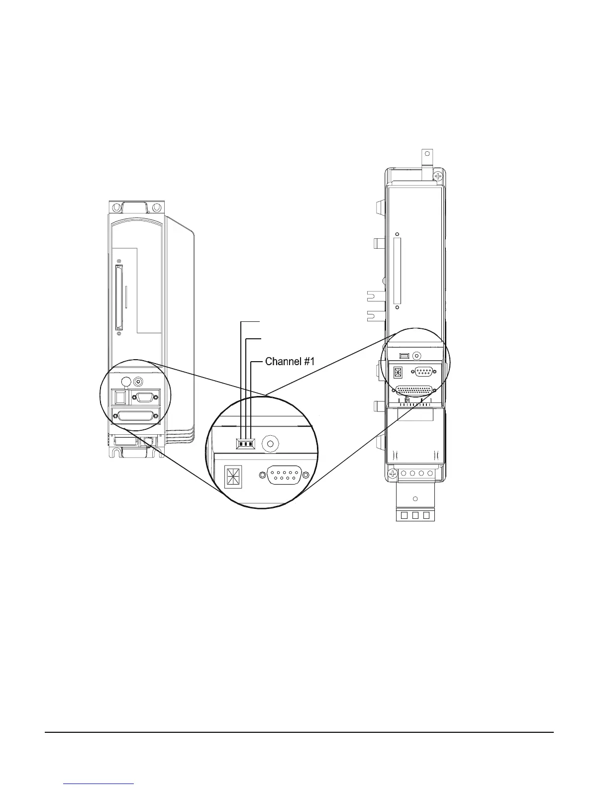
Diagnostic Analog Output Test Points
The DGNE cable was designed to be use with either an oscilloscope or a meter. The wires are
different lengths to avoid shorting to each other. However, if signals do get shorted to GND,
the drive will not be damaged because the circuitry is protected.
Figure 96: Diagnostic Output Test Points
Channel #2
Analog GND
MDS Drive Modul
e
VDC
10-3 0
J6
+
SERIAL J4
OUTPUT
COMMAND
INP UT
3
- 21 14 32
J5
RESET
VDC
10-3 0
J6
+
SERIAL J4
OUTPUT
COMMAND
INP UT
3
- 21 14 32
J5
SERIAL
COMMAND
RESET
SERIAL
COMMAND
EN Drive

Table of Contents

Questions and Answers:

Question and Answer IconNeed help?

Do you have a question about the Control Techniques FM-3 and is the answer not in the manual?

Control Techniques FM-3 Specifications

General IconGeneral
BrandControl Techniques
ModelFM-3
CategoryNetwork Hardware
LanguageEnglish