EasyManua.ls Logo

Control Techniques UD70 User Manual

Control Techniques UD70
154 pages
To Next Page IconTo Next Page
To Previous Page IconTo Previous Page
Page #71 background imageLoading...
Page #71 background image
UD70
Issue code: 70nu2
Serial communications 6-11
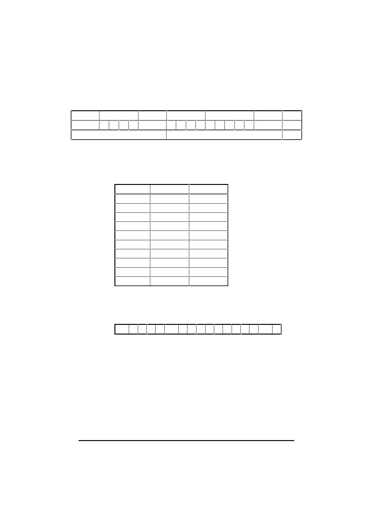
The message will be:
Control Address Control Parameter Data Control BCC
EOT 1 1 2 2 STX 0 1 2 1 3 4 . 5 ETX 0
Not included in the calculation Included in the calculation Result
The first character of the BCC calculation is 0 0 (00110000 in binary), the value
of which is taken as a starting or result value. The next character is 1 1
(00110001 in binary), which now has the exclusive OR (XOR) operator act
upon it. With the previous result value, a new result occurs of 00000001 in
binary.
The complete calculation is show in the table below:
Character Binary Value XOR result
0 0011 0000
1 0011 0001 0000 0001
2 0011 0010 0011 0011
1 0011 0001 0000 0010
0010 1101 0010 1111
3 0011 0011 0001 1100
4 0011 0100 0010 1000
. 0010 1110 0000 0110
5 0011 0101 0011 0011
ETX 0000 0011 0011 0000
The final value is the BCC, provided that its equivalent decimal value exceeds
31 (ASCII characters from 00 to 31 are used as control codes).
When the final
XOR result produces a decimal value less than 32, 32 is added.
In this example, 0011 0000 is 48 decimal which is above 31, so this is the final
BCC value. 48 decimal is the character 0. The complete message will be:
EOT 1 1 2 2 STX 0 1 2 1 - 3 4 . 5 ETX 0
Example
QuickBasic program to calculate BCC
mess$ = CHR$(4)+”1122”+CHR$(2)+”0125”+”-34.5”+CHR$(3)
bcc% = 0
FOR n% = 7 to LEN(mess$)‘start at the character after ‘chr$(2).
bcc% = bcc% XOR ASC(MID$(mess$, n%, 1))
NEXT
IF bcc% < 32 THEN bcc% = bcc% + 32
mess$ = mess$ + CHR$(bcc%)
PRINT mess$
In
DPL, the ANSIREAD and ANSIWRITE functions automatically calculate
the BCC.

Table of Contents

Other manuals for Control Techniques UD70

Question and Answer IconNeed help?

Do you have a question about the Control Techniques UD70 and is the answer not in the manual?

Control Techniques UD70 Specifications

General IconGeneral
BrandControl Techniques
ModelUD70
CategoryControl Unit
LanguageEnglish

Summary

Safety Information

General Information

Introduction to UD70 and DPL Toolkit

UD70 Overview and DPL Toolkit Basics

Explains the UD70 as a microcomputer for Unidrive flexibility and the DPL Toolkit for software development.

UD70 Memory and PC Requirements

Details UD70 memory storage and minimum PC specifications for DPL Toolkit.

Technical Data and User Knowledge

Lists UD70 technical specifications and assumes basic Windows knowledge for users.

Installation and Configuration

Installation Procedure

Instructions for physically fitting the UD70 module into the Unidrive.

System Configuration and DPL Toolkit Setup

Details host PC connections (RS232) and installing the DPL Toolkit.

DPL Toolkit Operations

DPL Toolkit Overview and File Management

Introduces the DPL Toolkit's capabilities and file handling procedures.

Editing Programs and Applying Styles

Covers editing code, using styles, and auto-indent features within the DPL Toolkit.

Compiling and Running Programs

Details the process of compiling DPL programs and executing them on the UD70.

Serial Communications

Serial Communications Introduction

Explains serial communication links using RS485 for UD70 systems.

Hardware Connections and ANSI Protocol

Details RS485 hardware connections, ANSI communications fundamentals, and frames.

Serial Modes and ANSI Instructions

Outlines various RS485 modes and available ANSI instructions for communication.

Reference Guide

UD70 Tasks and Programming Structures

Explains different task types (INITIAL, BACKGROUND, CLOCK) and their roles in UD70 programming.

DPL Instructions and Functions Reference

Details various DPL programming instructions and mathematical/signal-processing functions.

UD70 Features

PLC Parameters and Feature Introduction

Introduces PLC parameters and the UD70's advanced position control and profile generation capabilities.

Encoder Lines, Position, and Controller Setup

Explains encoder line units, position calculation, and enabling the position controller.

Default Values and Parameter Descriptions

Details default reset values and provides descriptions for various UD70 parameters.

Logic Diagrams and Digital Lock Control

Illustrates logic diagrams for position control and explains digital lock functions.

Cam Function and Reference Switching

Describes the cam function for slave axis control and switching between control modes.

Timer/Counter Unit and Digital I/O Ports

Details the UD70's timer/counter unit and digital I/O port functionality.

Memory Storage and RS232 Communications

Covers non-volatile memory storage and using the RS232 port for Drive-to-Drive communication.

Diagnostics and Error Handling

Run-time Errors and Trip Codes

Explains run-time errors, their causes, and provides a list of trip codes with their actions.

Compiler Errors and Advanced Error Handling

Lists compiler error messages and details advanced error handling using the ERROR Task.

UD70 Parameters

Set-up Parameters and RS485 Modes

Details UD70 set-up parameters and the various RS485 port modes available.

Virtual Parameters and Control Words

Explains virtual parameters and the function of control and status words.

General-Purpose Parameters and I/O Box Configuration

Lists general-purpose parameters and details I/O box configuration through menus.

Related product manuals