UD70
Issue code: 70nu2
6-14 Serial communications
Mode 12
Reserved
Mode 13
Modbus – RTU (slave mode only)
Mode 14
Modbus – ASCII (slave mode only)
The Modbus RTU and ASCII slave modes support the functions Read
Multiple Registers, Preset Single Registers and Preset Multiple Registers.
This mode limits the number of consecutive registers to 20, and the node
address range is limited from 11 to 99.
Contact your local Drive Centre for information about the Modbus
Protocol.
Note
There is minimal data integrity checking with modes 2, 3
and 4.
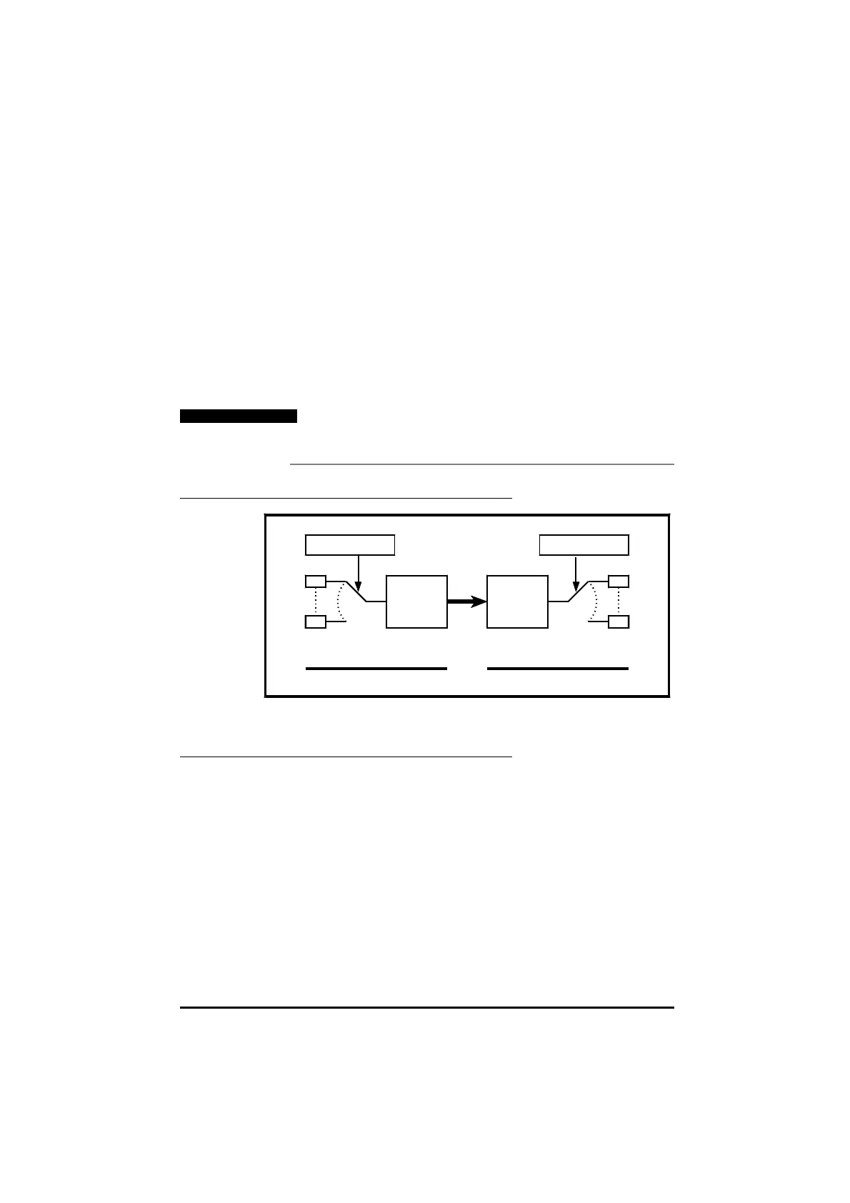
Using Modes 2 and 3
UD70 operating in Mode 2 UD70 operating in Mode 3
Source
Scale
±16000
Any parameter Serial link
Destination
Any parameter
Scale
#xx.xx
Functions of Modes 2 and 3Functions of Modes 2 and 3
Using Modes 6, 7, 8 and 9
In Modes 6, 7 or 8, it is possible to use the UD70 as an ANSI master device
controlling other UD70 modules, MD29 cards, Drives or other ANSI compliant
devices. This facility may alleviate the need for a custom computer or PLC
to control a system or process. When an I/O Box is used, there may be no
need for a PLC in a system.
Modes 6 to 9 also allow you to create custom serial protocols which you
may use for communicating with non-
ANSI compliant devices such as
intelligent display modules, etc.
The
ANSI RS485 port is buffered as follows:
Receive: 60 bytes
Transmit: 25 bytes