35
Figure 3-12 Wiring Bulkhead Cover
(c) Save the bulkhead cover and screws, and attach the cover
to the left side of the wirebox after the wirebox is attached
to the inverter enclosure. Covers may be required in the
future if an inverter or wirebox is to be removed during
servicing (see step 6,
(d) Figure
3-15). Tool required: No.2 Phillips head screwdriver
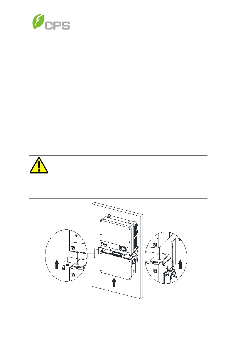
Step 4 Secure the wirebox to the main enclosure by using the M6x18
screws (4pcs) to fasten the wirebox. (see Figure 3-13). Tool
required: No.3 Phillips head screwdriver or 10mm Wrench,
torque value of 4 Nm (35.4in-lbs)
Figure 3-13 Installation of the Wiring Box
WARNING:
Ensure the M6x18 screws (4pcs) installed in Step 4 above are
properly torqued and the area under the bolt-head is clear of
paint. This connection provides an electrical ground bond of the
wirebox to the upper/main enclosure.