14
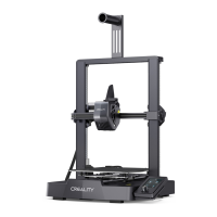
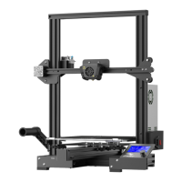
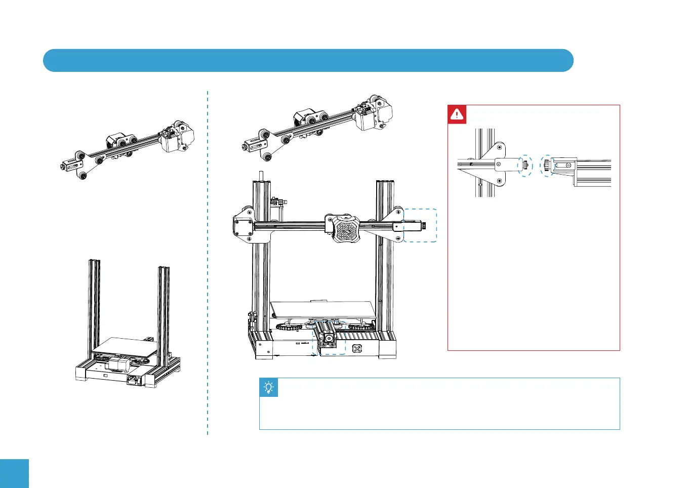
6. Install the Z-axis Gantry Assembly and Adjust X-axis and Y-axis Drive Belt Tension
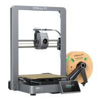
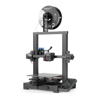
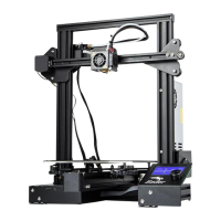
Assembled Part After Step 5
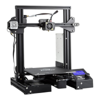
Assembled Part After Step 2
Back
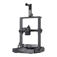
A
B
Front
A
B
● Turn the X-axis and Y-axis tensioner
knobs to adjust the belt tension.
● The belts should be taught but not over-
tight or too slack. When you press down
the drive belt, you should feel some
spring in the belt.
● If the belts are too lose they can slip
during printing ruining the result.
● If the belts are too tight they will over
stress the pulleys and motors or even
break.
● Place the lower V rollers into the grooves on the outside of the Z profiles.
● Locate the lead screw in the Brass nut on the XE Assembly and turn by hand to
screw the gantry down while guiding the other V rollers into the Z profile grooves.
● Adjust the tension of the X and Y axes drive belts as shown above.