© 2021 All rights reserved. Data subject to change without notice. 41
Rev. C | 2021.12 FCS - Installation Manual
The status of a channel is indicated by colours and text added to the end of the line as
follows:
COLOUR TEXT LED INDICATORS* DESCRIPTION
Green All are Green Channel is working normally
Green d All are Green Channel is disabled
Yellow L Status 1 is Red Channel is in low alarm
Orange M
Status 1 & 2 are
Red
Channel is in mid alarm
Red F Fault is Red Channel is in a Fault condition
Red C Fault is Red
Controller cannot communicate
with channel/transmitter
Red H
Status 1, 2 & 3 are
Red
Channel is in high alarm
Red S
Status 1, 2 & 3 are
Red
Channel has a STEL alarm
Red T
Status 1, 2 & 3 are
Red
Channel has a TWA alarm
Red I
Status 1, 2 & 3 are
Red
Channel has an IDLH alarm
*exclusive of other possible statuses occurring at the same time
Relay, Strobe, Horn and Audible Status Bar Operation
The FCS has four internal SPDT dry contact relays labeled RL1, RL2, RL3 and RL4.
Strobe, horns and the internal audible buzzer are also counted as relays.
The FCS may also have remote relays (RLY-4 and/or RLY-8) connected to it.
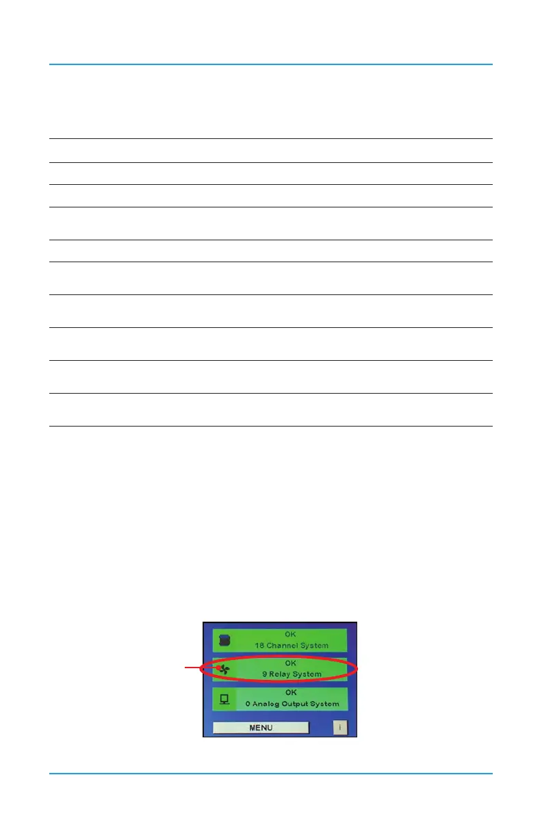
The Relay Status Bar on the main display of the FCS shows a summary of the status of the
relays, which includes the internal relays, remote relays and any remote strobes and horns. If
the relays are in different statuses, it will display the three most important statuses in order
from left to right. The bar will also change colour depending on the severity of the status.
This example indicates no relays are active and none are in ON or OFF delay:
Press the
icon here