4 — PROGRAMMABLE PARAMETERS
pg. 79
Return to TOC Curtis AC F4-A Motor Controller – August 2020
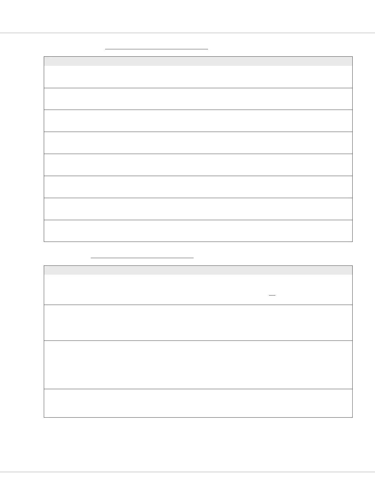
APPLICATION SETUP/HYDRAULICS — LOWER SETTINGS MENU
PARAMETER ALLOWABLE RANGE DEFAULT DESCRIPTION
Lower Input
Lower_Pot_Percent
0x3044 0x00
0.0 – 100.0 %
0 – 1000
Read Only Lower pot input after source selection and before mapping as a
percentage.
Mapped Lower
Mapped_Lower_Throttle
0x4FD9 0x00
0.0 – 100.0 %
0 – 32767
Read Only Hydraulics lower throttle after mapping.
Lower Command
Lower_Throttle
0x3725 0x00
0.0 – 100.0 %
0 – 32767
Read Only Proportional driver current request.
Lower Min Input
Lower_Deadband_Percent
0x3711 0x00
0 – 100 %
0 – 1000
5 % Input voltage percentage below which throttle is made 0.
Lower Max Input
Lower_Max_Percent
0x3714 0x00
0 – 100 %
0 – 1000
95 % Input value corresponding to 100% throttle.
Lower Map Shape
Lower_Map
0x3713 0x00
0 – 100 %
0 – 32767
35 % Denes sensitivity of input. Lower value results in lesser output
variation to input. Set at 50% for linear response.
Lower Offset
Lower_Offset
0x3715 0x00
0 – 100 %
0 – 32767
0 % Minimum lower throttle command after input becomes greater
than lower_deadband_percent parameter.
Lower Filter
Lower_Throttle_Filter
0x3C3D 0x00
0.1 – 100.0 Hz
1 – 1000
10.0 Hz Sets low pass lter cutoff frequency for lowering proportional
valve. Higher values make it more responsive, lesser values make
it less responsive to input variations.
APPLICATION SETUP/HYDRAULICS — LOAD HOLD VALVE SETTING MENU
PARAMETER ALLOWABLE RANGE DEFAULT DESCRIPTION
Load Hold Valve Driver
Load_Hold_Driver
0x3C41 0x00
0 – 5
0 – 5
0
[PCF]
Select the PWM Driver to which load hold valve is connected.
Changes require cycling the keyswitch to take effect.
The default value, 0, does not select a driver.
Shown as Driver 3 in Figure 6, Basic Wiring Diagram
Load Hold Valve Enable On
Lift
Load_Hold_Enable_On_Lift
0x37E0 0x00
Off/On
0 – 1
Off 0 - The load hold valve is disabled on lift. Specify 0 if the
application does not use a load-hold valve.
1 - The load hold is enabled on lift. Specify 1 if the application
uses a load-hold valve.
Note: Set Load_Hold_Open_Delay to congure the delay time.
Load Hold Opening Delay
Load_Hold_Open_Delay
0x370E 0x00
0 – 2000 ms
0 – 2000
0 ms This parameter delays opening of the load-hold valve when the
hydraulic pump is turned on (i.e., the lift command).
0 ms: The load-hold valve is continually kept closed (i.e.,
the load-hold driver is off) when the DC pump motor
is turned on.
8-2000 ms: The duration of time before opening the load hold
valve after the DC pump motor is turned on.
Load Hold Valve Driver
Voltage
Load_Hold_Driver_Voltage
0x3005 0x00
0 – 100 %
0 – 32767
0 % Denes the battery-compensated commanded PWM of Load Hold
Valve Driver.
Higher values will open the valve faster/rmer (similar to driving a
contactor coil close when applying 100%).
 Loading...


