4 — PROGRAMMABLE PARAMETERS
Curtis AC F4-A Motor Controller – August 2020 Return to TOC
pg. 90
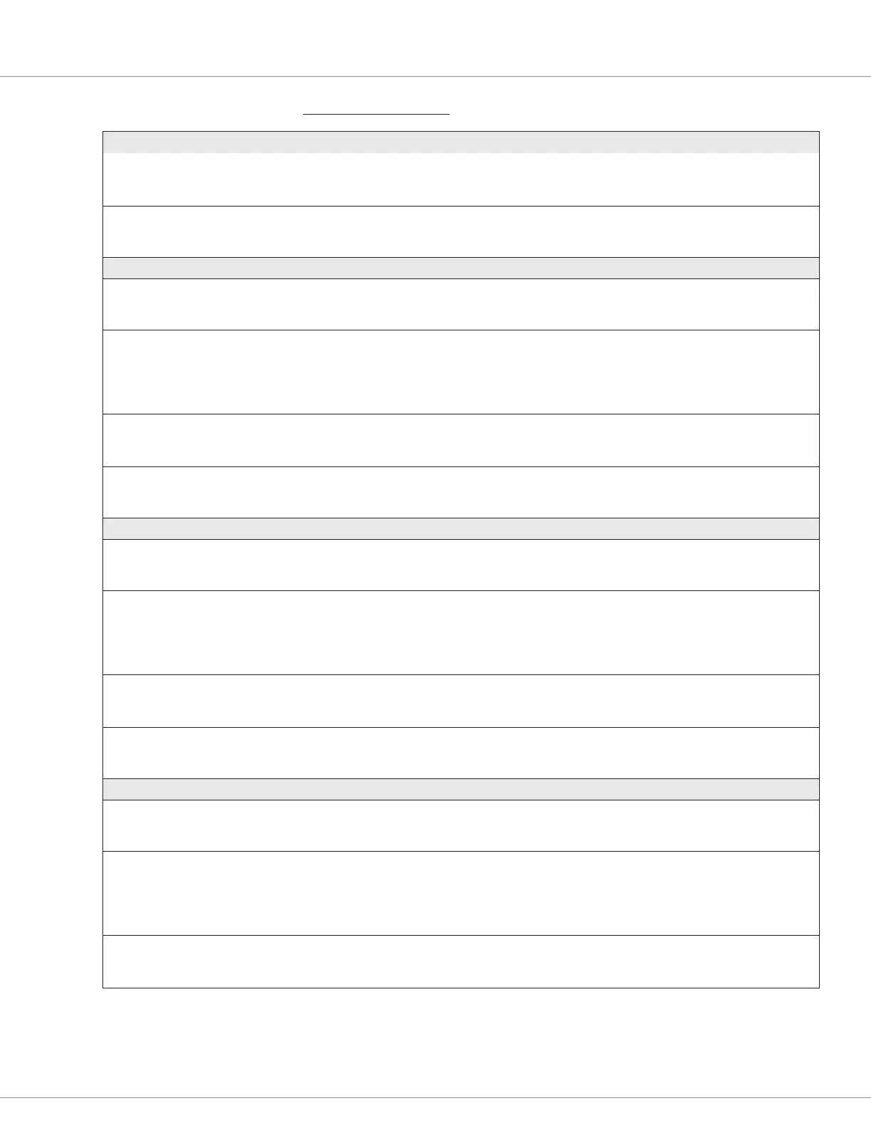
CONTROLLER SETUP — INPUTS MENU, cont’d
PARAMETER ALLOWABLE RANGE DEFAULT DESCRIPTION
Low
Analog_Input_2_Low
0x32F5 0x00
0.0 – 7.0 V
0 – 700
0.0 V The minimum input voltage before a fault is declared.
This voltage represents the 0% point for the normalized inputs.
High
Analog_Input_2_High
0x32F6 0x00
0.0 – 7.0 V
0 – 700
7.0 V The maximum input voltage before a fault is declared.
This voltage is the 100% point for the normalized inputs.
Analog 3 menu
Voltage
Analog_Input_Volts_3
0x3B30 0x00
–327.68 – 327.67
–32768 – 32767
Read Only
V
Voltage at pin 31 (as the motor encoder-A signal in Fig 6).
Percent
Analog_Input_Percent_3
0x3B3B 0x00
0.0 – 100.0 %
0 – 1000
Read Only Voltage on a 0-100 percentage basis, pin 31.
The percentage of the voltage at pin 31 based upon the High and
Low settings, i.e., the percent of:
((analog_input_volts_3) – (analog_input_3_low)) /
((analog_input_3_high) – (analog_input_3_low))
Low
Analog_Input_3_Low
0x32F7 0x00
0.0 – 7.0 V
0 – 700
0.0 V The minimum input voltage before a fault is declared.
This voltage represents the 0% point for the normalized inputs.
High
Analog_Input_3_High
0x32F8 0x00
0.0 – 7.0 V
0 – 700
5.0 V The maximum input voltage before a fault is declared.
This voltage is the 100% point for the normalized inputs.
Analog 4 menu
Voltage
Analog_Input_Volts_4
0x3B31 0x00
–327.68 – 327.67
–32768 – 32767
Read Only
V
Voltage at pin 32 (as the motor encoder-A signal in Fig 6).
Percent
Analog_Input_Percent_4
0x3B3C 0x00
0.0 – 100.0 %
0 – 1000
Read Only Voltage on a 0-100 percentage basis, pin 32.
The percentage of the voltage at pin 32 based upon the High and
Low settings, i.e., the percent of:
((analog_input_volts_4) – (analog_input_4_low)) /
((analog_input_4_high) – (analog_input_4_low))
Low
Analog_Input_4_Low
0x32F9 0x00
0.0 – 7.0 V
0 – 700
0.0 V The minimum input voltage before a fault is declared.
This voltage represents the 0 % point for the normalized inputs.
High
Analog_Input_4_High
0x32FA 0x00
0.0 – 7.0 V
0 – 700
5.0 V The maximum input voltage before a fault is declared.
This voltage is the 100 % point for the normalized inputs.
Analog 5 menu
Voltage
Analog_Input_Volts_5
0x3B32 0x00
–327.68 – 327.67
–32768 – 32767
Read Only
V
Voltage at pin 9.
Percent
Analog_Input_Percent_5
0x3B3D 0x00
0.0 – 100.0 %
0 – 1000
Read Only Voltage on a 0-100 percentage basis, pin 9.
The percentage of the voltage at pin 9 based upon the High and
Low settings, i.e., the percent of:
((analog_input_volts_5) – (analog_input_5_low)) /
((analog_input_5_high) – (analog_input_5_low))
Low
Analog_Input_5_Low
0x32FB 0x00
0.0 – 30.0 V
0 – 3000
0.0 V The minimum input voltage before a fault is declared.
This voltage represents the 0 % point for the normalized inputs.
Quick Links:
Voltage rottle p.136
3-Wire rottle p.135
2-Wire rottle p.135
Fig. 6 p.10
 Loading...


