4 — PROGRAMMABLE PARAMETERS
pg. 91
Return to TOC Curtis AC F4-A Motor Controller – August 2020
CONTROLLER SETUP — INPUTS MENU, cont’d
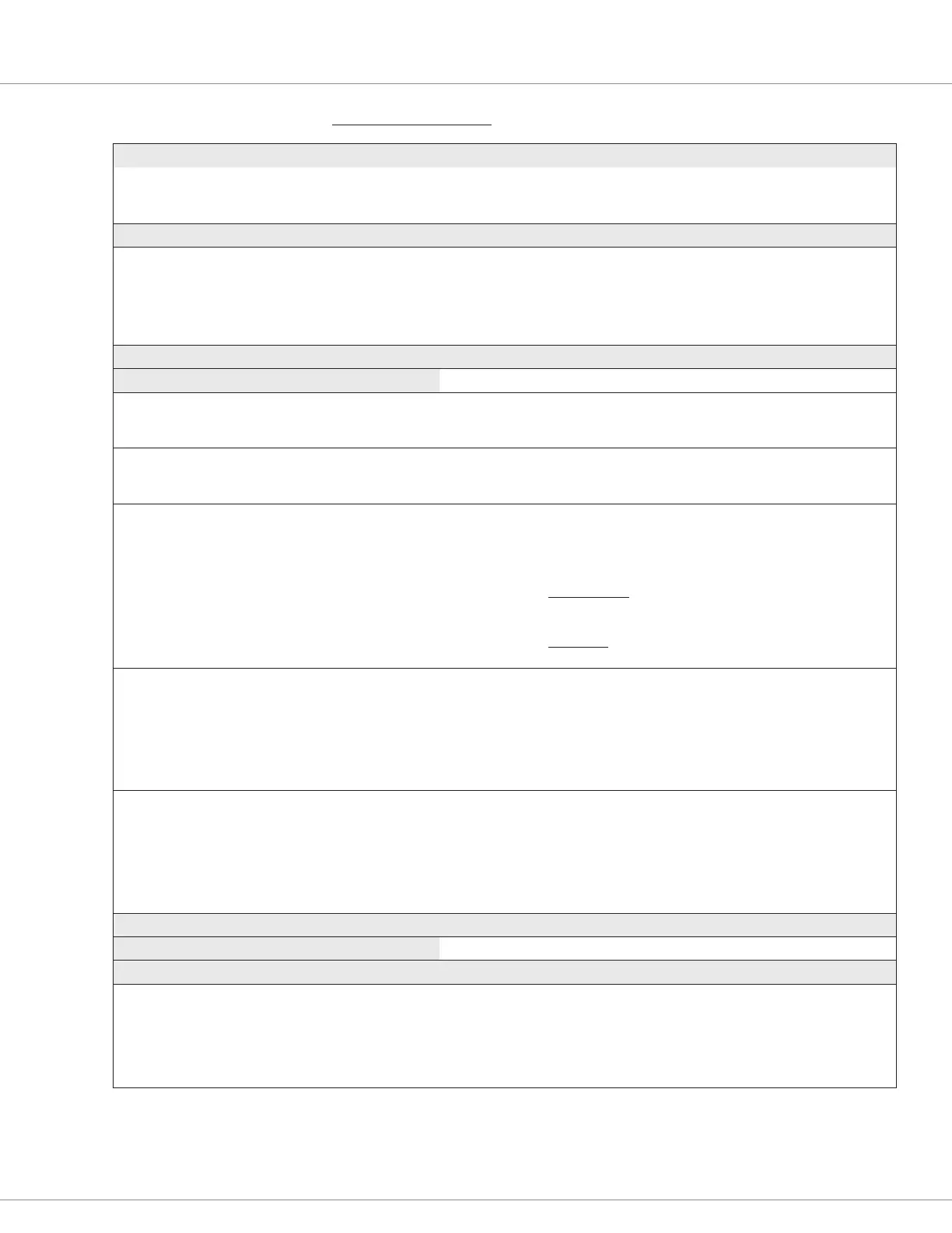
PARAMETER ALLOWABLE RANGE DEFAULT DESCRIPTION
High
Analog_Input_5_High
0x32FC 0x00
0.0 – 30.0 V
0 – 3000
30.0 V The maximum input voltage before a fault is declared.
This voltage is the 100 % point for the normalized inputs.
Analog 6 menu
Analog 6 Type
Analog_Input_6_Type
0x3310 0x00
Enumeration
0 – 3
Voltage Congure the Analog 6 input by throttle or load type.
0 – Voltage (Hall-effect or voltage throttle)
1 – 3-Wire Pot Wiper (3-wire resistive potentiometer throttle)
2 – 2-Wire Pot Wiper (2-wire resistive potentiometer throttle)
3 – Voltage with Supply (a non-throttle load alternative)
Analog 6 menu
Parameters for Voltage selection Reference the Voltage Throttle section, Chapter 6
Analog 6 Type
Analog_Input_6_Type
0x3310 0x00
Voltage
(selection menu)
– Selecting the Voltage option opens the menu to its corresponding
monitor variables and the low/high parameters.
Voltage
Analog_Input_Volts_6
0x3B33 0x00
–327.68 – 327.67
–32768 – 32767
Read Only
V
The analog voltage at the input pin 15.
Percent
Analog_Input_Percent_6
0x3B3E 0x00
0.0 – 100.0 %
0 – 1000
Read Only
%
The percentage of the voltage at pin 15 based upon the
High and Low settings, i.e., the percent of:
((analog_input_volts_6) – (analog_input_6_low)) /
((analog_input_6_high) – (analog_input_6_low))
Voltage Throttle usage: reference the Forward Min/Max & Reverse
Min/Max Input parameters located in the Application Setup »
Throttle menu.
Brake input usage: reference the Brake Min/Max Input
parameters located in the Application Setup » Brake menu.
Low
Analog_Input_6_Low
0x32FD 0x00
0.0 – 11.0 V
0 – 1100
0.0 V The minimum input voltage before a fault is declared. When the
Analog 6 Type selection is voltage, this set point represents the
0% point for the normalized input.
Triggers the Throttle Input fault (0x2210) when the voltage reading
is below this input voltage reading, if Throttle_Source = 6.
Triggers the Brake Input fault (0x2310) when the voltage reading
is below this input voltage reading, if Brake_Source = 6.
High
Analog_Input_6_High
0x32FE 0x00
0.0 – 11.0 V
0 – 1100
11.0 V The maximum input voltage before a fault is declared. When the
Analog 6 Type selection is voltage, this set point represents the
100% point for the normalized input.
Triggers the Throttle Input fault (0x2210) when the voltage reading
is above this input voltage reading, if Throttle_Source = 6.
Triggers the Brake Input fault (0x2310) when the voltage reading
is above this input voltage reading, if Brake_Source = 6.
Analog 6 menu
Parameters for 3Wire Pot selection Reference the 3-wire potentiometer throttle section, Chapter 6.
Potentiometer 6 (wiper) & 1 (high)
Analog 6 Type
Analog_Input_6_Type
0x3310 0x00
3Wire Pot
(selection menu)
– Selection of the 3-Wire Pot opens the Nominal Resistance parameter.
Note, When conguring Analog Input 6 as a 3-Wire Potentiometer
input, it becomes the wiper (pin 15) and is paired with Analog 1
(pin 16) as the wiper 5V supply voltage (high). The Programmer
app will automatically adjust the menu to match this parameter
conguration.
Quick Links:
Voltage rottle p.136
3-Wire rottle p.135
2-Wire rottle p.135
Fig. 6 p.10
 Loading...


