Chapter 8: Troubleshooting Noise Problems 153
Warning
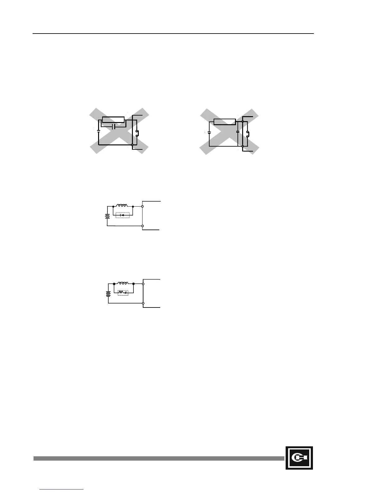
The following two protection methods should be avoided. Each of these methods can be effective in
removing the sparks when power to the inductive load is turned off. However when power is turned on
to the inductive load there will be a high inrush current applied across the relay contacts as they are
mating. Since all relay contacts have some bounce while mating, arcing will occur and potentially melt
the relay contact points. This is the reason for having the resistor in the RC network described earlier.
Inductive load
C
COM
OUT
Power
Inductive load
C
COM
OUT
Power
• Transistor Output Module—it is best to attach a flyback diode parallel to the inductive load,
as close as possible to the load. In this configuration output switching frequency should be
held to less than 20 times per minute.
• SSR Output Module—attach a surge suppressor parallel to the inductive load, as close as
possible to the load. In this configuration output switching frequency should be held to less
than 20 times per minute.
Transistor out
ut module
COM
OUT
Inductive load
SSR out
ut module
COM
OUT
R
C
Inductive load
Artisan Technology Group - Quality Instrumentation ... Guaranteed | (888) 88-SOURCE | www.artisantg.com