178 D50 PLC User's Manual
Programming Procedure
The high-speed counter is very easy to use, and requires very little programming. The following steps
outline the standard programming procedure to set up, turn on, and use the D50 high speed counter.
1. Configure the type of counter to be used by turning on the necessary mode bits in the MODE
register. To set the counter up for 2-phase or Up/Down mode, set bit 6 (UD/2). To configure
the counter as a ring counter, set bit 5 (RING). If the counter uses only a single input, and is
not a ring counter, leave both bits off.
2. Enable the inputs required by the counter to count. On channel 0, set bit 0 (R0) of its MODE
register R4 if the input on R0.0 will be a count input. Likewise set bit 1 (R1) if the input on
R0.1 will be a count input (for example, for a down-counter or 2-phase counter). On channel
1, set bit 0 (R4) and bit 1 (R5) of its MODE register R19 based on which inputs, R0.4 and
R0.5, will be used as count inputs. The Preset bits PRST are should be set if an external input
will be used to reset the counter value.
3. Set the start value STR and the end value END for the counter, based on the application. The
STR value will be used to reset the counter, while the END value is used by the comparison
register HFLAG.
4. Turn on the counter channel. This is done simply by setting the RUN bit, bit 7, of the MODE
register for that channel.
5. Use either the comparison register (HFLAG) or the D50 PLC’s comparison instructions (>, <,
=, >=, <=, <>) on the present value (PV) of the counter in the program, based on the
application.
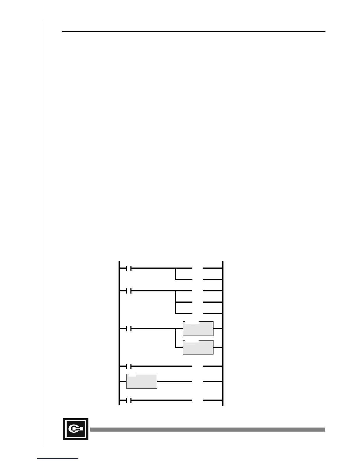
The following ladder program illustrates the above 5-step procedure for a simple counter application.
For this example, a standard Up Counter is programmed, with an end value of 100. At the count of
9000, the program turns on the D50 PLC’s first output R15.0, and at the count of 10000, the second
PLC output R15.1 is turned on. Since this is an Up Counter, the first input of channel 0 is used to
count input pulses.
D>
F1.0 R4.6
(RST)
DLET
D = R5
S = 0
Set the Start Value (STR) to 0
Turn OFF 2-phase mode
R4.5
(RST)
Turn OFF Ring Count mode
F1.0 R4.0
(SET)
Turn ON Up input 0 (R0.0) for up count
R4.1
(RST)
Turn OFF Down input 1 (R0.1)
R4.2
(RST)
Turn OFF Preset input 2 (R0.2)
DLET
D = R7
S = 10000
Set the End Value (END) to 10000
F1.0
F1.0 R4.7
(SET)
Turn ON the high-speed counter
D = R9
S = 9000
Turn ON R15.0 at 9000 counts
R15.0
(OUT)
R26.0 R15.1
(OUT)
Turn ON R15.1 when PV = END
Artisan Technology Group - Quality Instrumentation ... Guaranteed | (888) 88-SOURCE | www.artisantg.com