32 D50 PLC User's Manual
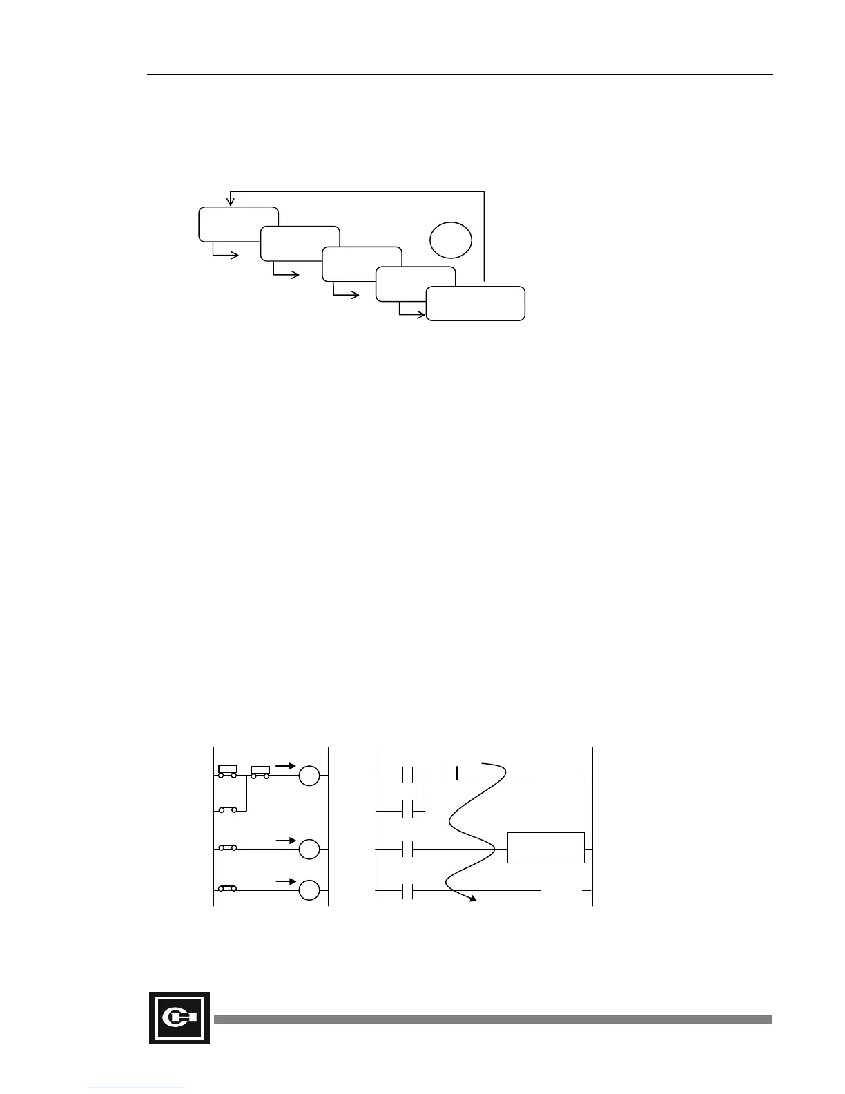
CPU Processing Procedure
Program Processing Procedure
The diagram above indicates the PLC program processing procedure. The CPU regularly repeats
procedure 1 through 5. This cycle is called 1 scan time.
1. Mandatory input/output processing
The internal force table is applied to internal/external I/O, turning forced I/O On or Off.
2. Input/output processing
Preserves the On/Off state of the external I/O and uses it as input in the next scan. (For
accurate processing, input should continue for more than 1 scan time.) The processed program
outputs are sent from the internal memory to the external modules.
3. Watchdog time initialization
The watchdog elapsed time value is set to 0. This value is the watchdog calculation point until
the next scan.
4. Program analysis
Executes the program from its first step to its final step and stores the internal/external output
in the working RAM.
5. Peripheral device signal processing
Stores data from communications module or peripheral device in the internal memory.
The following illustration shows the difference between the relay board and PLC sequence processing.
The relay carries out all sequences simultaneously while the PLC processes sequentially throughout
the program.
1. Mandatory
input/output
2. Process
input/output
3. Watchdog
time
→ 0
4. Program
analysis
5. Peripheral device
signal processing
1 scan
time
LS1 LS2
X1
X1
T1
T1
Y1
X1
TIM CH = 0
V = 100
M0.0
(OUT)
R15.0
(OUT)
R0.1 R0.2
M0.0
M0.0
TC0
Processing of relay sequence
(parallel process)
Processing of PLC program
(serial process)
Artisan Technology Group - Quality Instrumentation ... Guaranteed | (888) 88-SOURCE | www.artisantg.com