Chapter 3: Product Specification 19
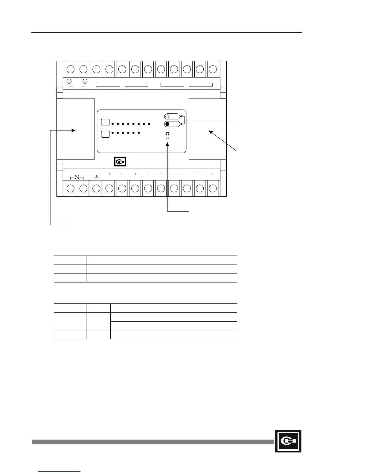
Name and Function of Controller Components
The mode switch has the following settings:
State Function
RUN CPU set in Run or Stop/Program Override mode.
PROG. CPU set in Stop/Program mode.
The Status LED’s provide the following information:
LED Color Function
On when the CPU is in Run mode.
RUN Green
Flashing when the CPU is in Stop/Program mode.
ERROR Red On when CPU has an error.
The I/O Expansion Port supplies a 10-pin connector for adding digital and/or analog expansion
modules to the base controller.
The RS485 Communication Port supports an RS485 connection for programming, configuring, and
monitoring the PLC. For communication with most RS232 peripherals, such as a personal computer,
an RS232/485 converter must be used. When placed on an RS485 network with other D50, D300, or
D320 PLC’s, the ends of the network should be properly terminated with 120 Ohm resistors to prevent
communication errors due to noise and reflections on the transmission line.
Programmable Controller
D50
DC 24V
OUT
C0
0
1
1
2
2
3
3
4
4
5
5
6
7
C
CCC
IN IN
IN
OUT
OUT OUT
RUN
ERR
RUN
STOP
01234567
012345
Cutler-Hammer
OUTGND
IN 100-240V
RS485 Communication Port
Mode Switch
Status LED’s
I/O Expansion Port
Artisan Technology Group - Quality Instrumentation ... Guaranteed | (888) 88-SOURCE | www.artisantg.com