Appendix B: Special I/O Functions 177
Bit Registers
Three of the configuration registers used by the high-speed counters are bit registers – each bit in the
register serves a different purpose. The three bit registers and the individual bit meanings are
described in further detail below.
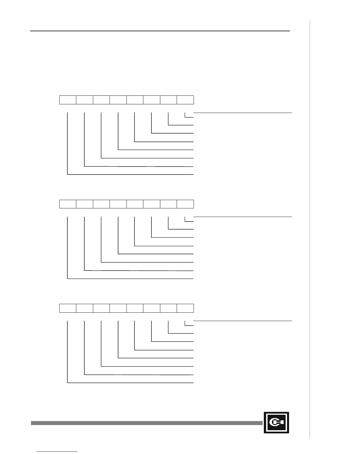
H0MODE – Mode Register R004
Bit #:
76543210
Bit Name:
RUN UD/2 RING PRST - R2 R1 R0
Description
Enable R0.0 as Up/Ph. A count input
Enable R0.1 as Down/Ph. B count input
Enable R0.2 as Preset input
Not Used
Preset Counter (STR PV)
Enable Ring Counter mode
Enable Up/Down or 2-phase mode
Run/Stop – Turn on Counter
H1MODE – Mode Register R019
Bit #:
76543210
Bit Name:
RUN UD/2 RING PRST - R6 R5 R4
Description
Enable R0.4 as Up/Ph. A count input
Enable R0.5 as Down/Ph. B count input
Enable R0.6 as Preset input
Not Used
Preset Counter (STR PV)
Enable Ring Counter mode
Enable Up/Down or 2-phase mode
Run/Stop – Turn on Counter
HFLAG – Comparison Register R026
Bit #:
76543210
Bit Name:
EQ1D GT1 LT1 EQ1 EQ0D GT0 LT0 EQ0
Description
PV = END on channel 0 (latched)
PV < END on channel 0
PV > END on channel 0
Unlatch EQ0 bit (PV = END)
PV = END on channel 1 (latched)
PV < END on channel 1
PV > END on channel 1
Unlatch EQ1 bit (PV = END)
Artisan Technology Group - Quality Instrumentation ... Guaranteed | (888) 88-SOURCE | www.artisantg.com