19/40
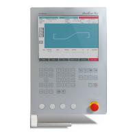
Bend data table
Product number
Material thickness
Graphic representation
of the prole
Material
Bending length
Tools selectionMaterial Sigma
ModEva Pac User Manual
April
2016
V2.3
l-alpha proGraMMinG
In this mode, the operator can define each step (length and angle) of a profile in a table.
In the bottom section of the page, the operator can see the profile being automatically
drawn as a function of the introduced data. The value of the internal radius is
automatically calculated as a function of the selected tools.
Setting inStructionS:
1. Touch the button and select neW Product in the list.
2. First select the material, enter its thickness and Sigma, enter the bending length, and
select the tools to be used for the part by touching their respective fields.
3. Touch the first field of the
LengtH column and introduce the value of 45.00 which
corresponds to the first length.
4. Touch the first field of the
angLe column and introduce the value of 90° which
corresponds to the first angle to be bent.
5. Proceed in the same manner for all steps and angles of the profile of section 1 (see
Creating a Part Program, page 16).
6. Touch the
Section field, enter the value of 2 and leave the field. This automatically
initializes a new page for programming section 2.
7. Proceed in the same manner as for section 1 to define lengths and angles values.
8. If a bend needs special functions, see Special functions for a bend, page 18.
9. Once all the segments and angles defines, go to the Bend 2D Page (see page 22).
→ Product Numerical
When introducing data in L-Alpha mode, simply begin from one of the
extremities of the profile and fill in the values of each face and angle one after
another, with the last face having no corresponding angle.
Selecting tools directly from the L-Alpha page places them automatically in the
middle of the machine. To change their position, see Tooling Management, page
12.