20/40
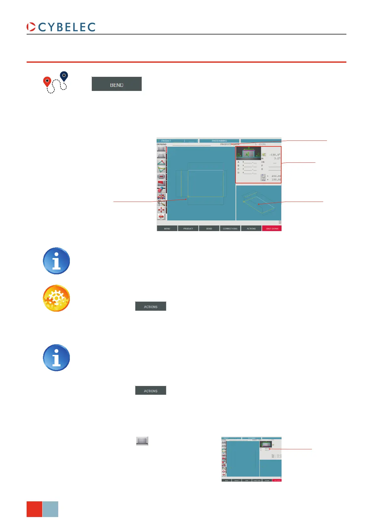
Working window
(here showing
two-dimensional view)
Display window
(here showing
axonometric view)
Tool window
(here showing add
rectangular face)
Product data eld
Base rectangle
dimensions
ModEva Pac User Manual
April
2016
V2.3
3d proGraMMinG (opTional, only for off-line verSion)
→ Product 3D
In this mode (available only on the ModEva software with 3D option), the operator can
conceive a part directly in 3 dimensions. The definitions of the different icons you will
encounter through these pages are described in the 3D Reference Manual, in chapter
Definition of the Icons.
Setting inStructionS:
1. Touch the button and select neW Product in the list.
2. Touch the
Product data field and select the material, enter its thickness and Sigma,
enter the bending length, and select the tools to be used for the part by touching
their respective fields.
Selecting tools directly from this window places them automatically in the
middle of the machine. To change their position, see Tooling Management, page
12.
3. Touch Quit to confirm the chosen values.
4. Touch the
button and select ModiFy 1F or ModiFy 2F. The difference
between the two functions is:
•
ModiFy 1F: Shows the product in plan mode (2D).
•
ModiFy 2F: Shows the product in plan mode and in axonometric mode (3D).
Touching the display window inverts the two-dimensional and the axonometric
views, allowing the operator to create his part in two or three dimensions.
5. Touch this button to add a
rectangular face. The base rectangle
appears in plan mode in the work
window as well as in axonometric
mode. The tool window is adapted.
6. Introduce the dimensions for a and B (in
our example: 150.00 and 200.00).