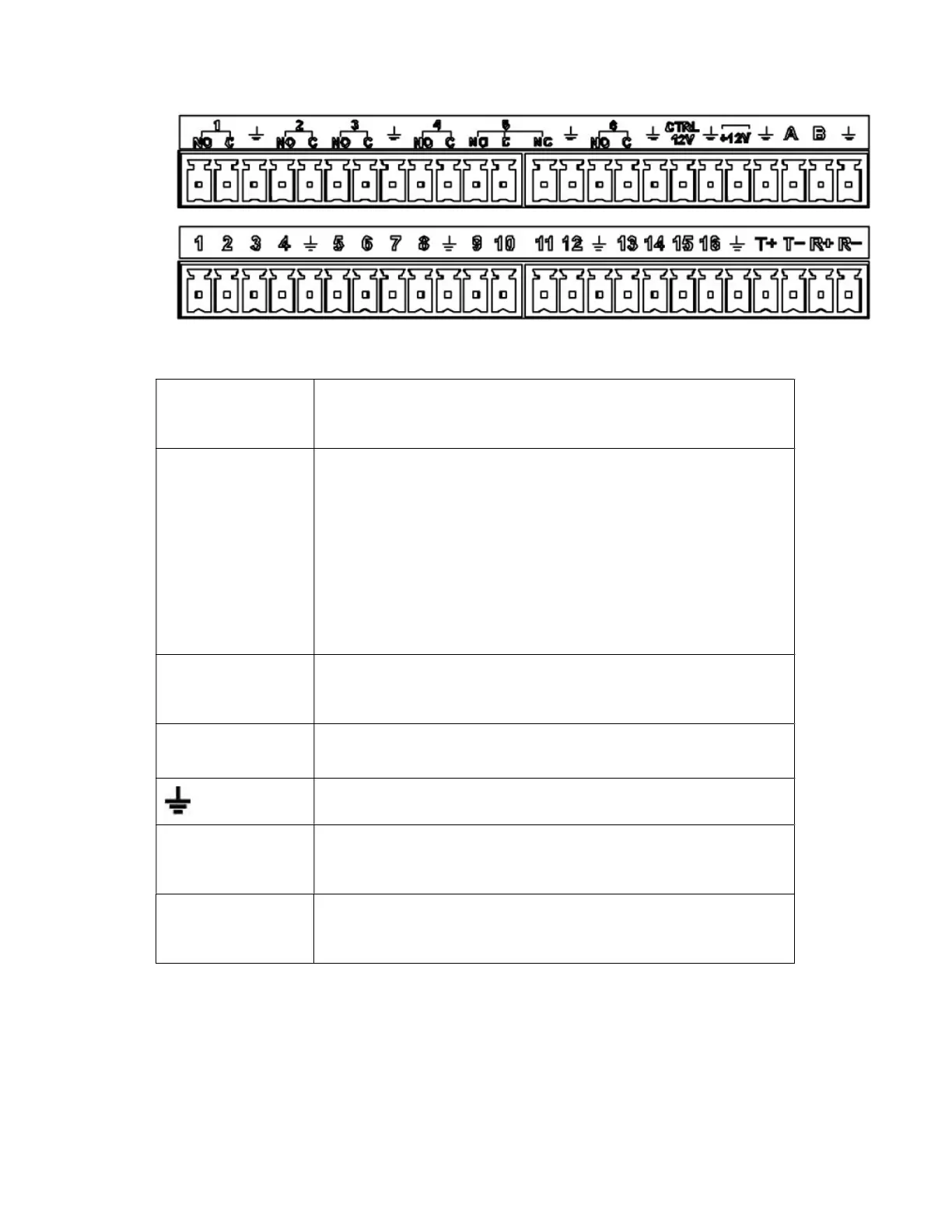
Figure 2-1
1,2,3,4,5,6,
7,8,9,10,11,
12,13,14,15,16
ALARM 1 to ALARM 16. The alarm becomes active in low voltage.
In the second line,
from the left to the
right:
NO1 C1,
NO2 C2,
NO3 C3,
NO4 C4,
NO5 C5,
NO6 C6.
There are six groups of normal open activation output (on/off button)
CTRL 12V Control power output. For external alarm, you need to close the
device power to cancel the alarm.
Voltage current;500mA.
+12V Rated current.
Voltage current;500mA.
Earth cable.
485 A/B 485 communication port. They are used to control devices such as
decoder. 120Ω should be parallel connected between A, B lines if
there are too many PTZ decoders.
T+,T-,R+,R- They are four-wire full-duplex RS485 port
T+ T-: output wire
R+ R-: input wire
2.7.2 Alarm Input Port
Please refer to the following sheet for more information.
Grounding alarm inputs. Normal open or Normal close type)
Please parallel connect COM end and GND end of the alarm detector (Provide
external power to the alarm detector).
Please parallel connect the Ground of the DVR and the ground of the alarm detector.