5.8.5.5 PTZ
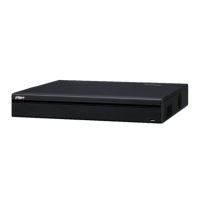
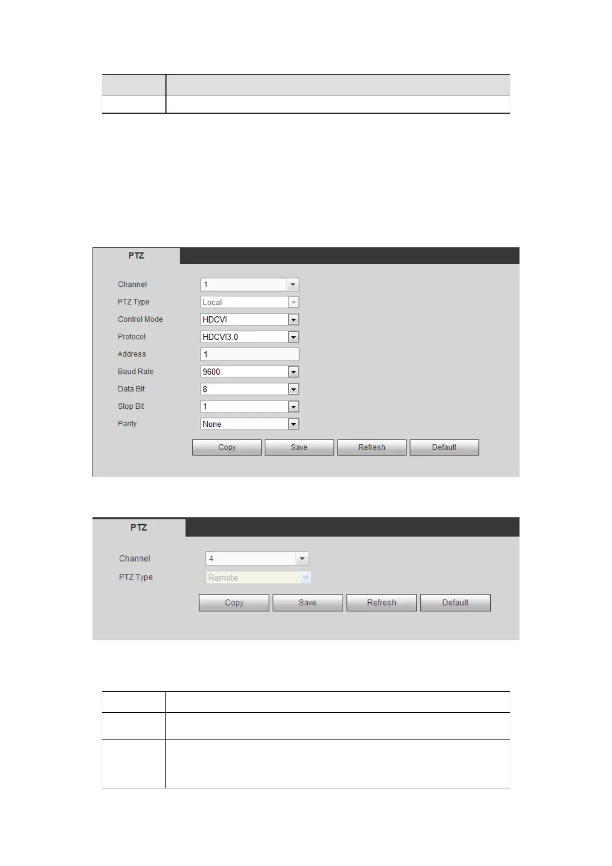
The PTZ interface is shown as in Figure 5-100 and Figure 5-101.
Before setup, please check the following connections are right:
PTZ and decoder connection is right. Decoder address setup is right.
Decoder A (B) line connects with DVR A (B) line.
Click Save button after you complete setup, you can go back to the monitor interface to
control speed dome.
Figure 5-100
Figure 5-101
Please refer to the following sheet for detailed information.
Select speed dome connected channel.
There are two types: local/remote. Please select local mode if you are
connect RS485 cable to connect to the Speed dome (PTZ). Please
select remote mode if you are connecting to the network PTZ camera.
 Loading...