17 | Technical data
Installer reference guide
293
ERLA11~16D + EBBH/X11+16D
Daikin Altherma 3 R W
4P643603-1B – 2022.05
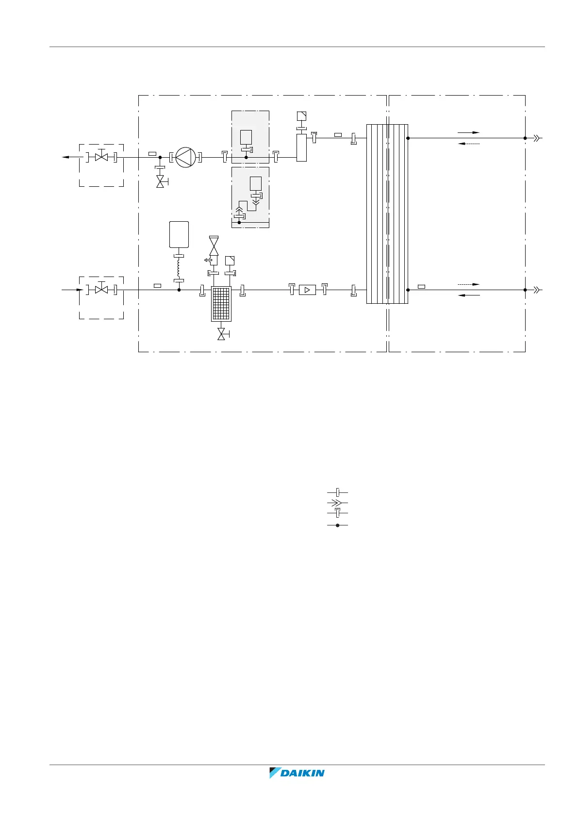
17.3 Piping diagram: Indoor unit
A
C
e
e
C
g
j
h
l
a2
a1
i
k
f
d
i
c1
b2
c2
b1
B
j
3D113750
R2T
R4T
B1PW
EBBH*
EBBX*
B1PW
B2L
R1T
R3T
A Water side B1PW Space heating water pressure sensor
B Refrigerant side B2L Flow sensor
C Field installed
a1 Space heating/cooling – Water IN (screw
connection, 1")
Thermistors:
a2 Space heating/cooling – Water OUT (screw
connection, 1")
R1T Heat exchanger – Water OUT
b1 Gas refrigerant IN (heating mode; condenser) R2T Backup heater – Water OUT
b2 Liquid refrigerant OUT (heating mode; condenser) R3T Liquid refrigerant
c1 Liquid refrigerant IN (cooling mode; evaporator) R4T Heat exchanger – Water IN
c2 Gas refrigerant OUT (cooling mode; evaporator)
d Plate heat exchanger Connections:
e Shut-off valve for service Screw connection
f Expansion vessel Flare connection
g Magnetic filter/dirt separator Quick coupling
h Safety valve Brazed connection
i Automatic air purge
j Drain valve
k Backup heater
l Pump

 Loading...


