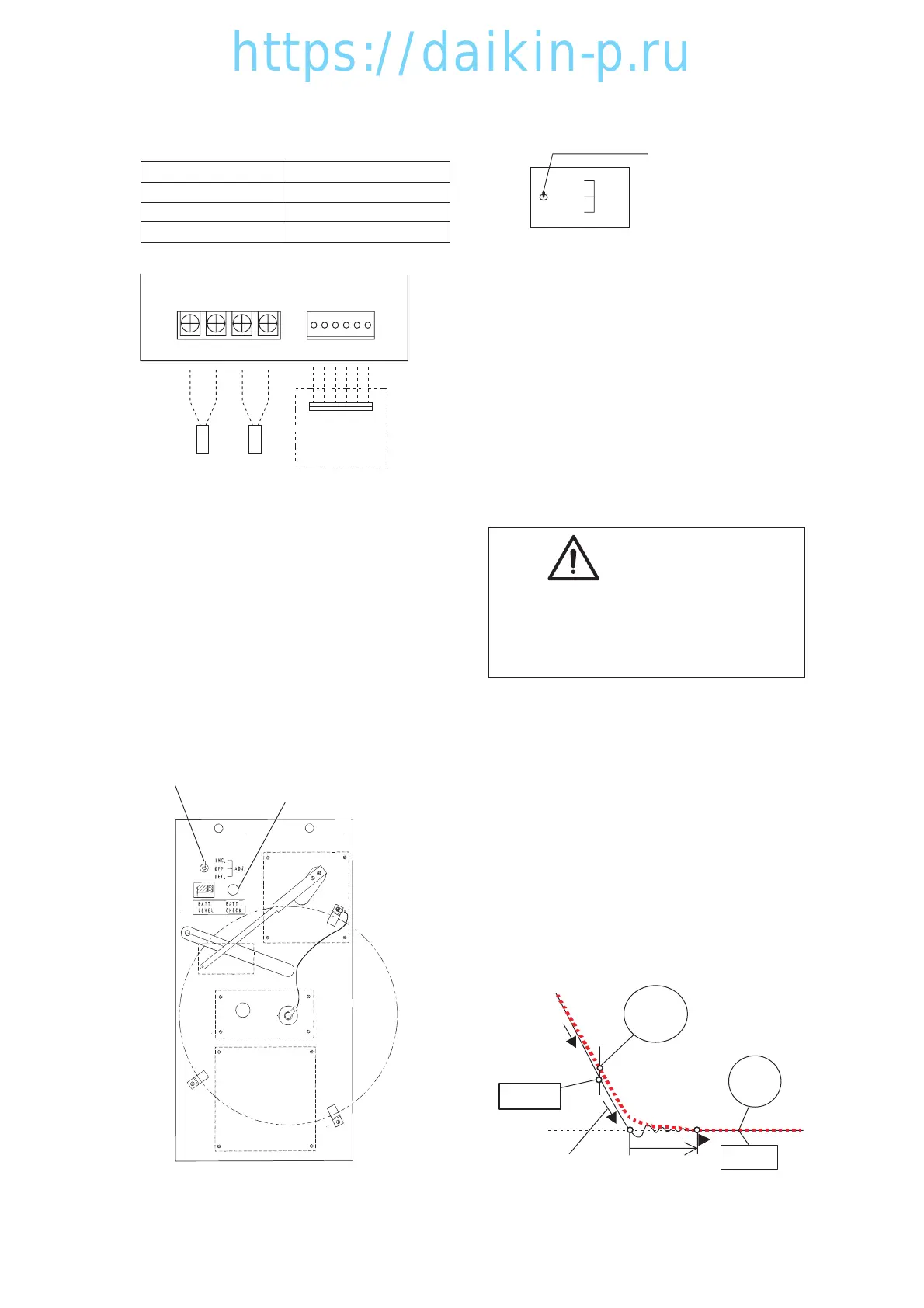
qCalibration switch
wBattery check button
5-2
(2) Devices and schematic wiring diagram
1) Devices
Device Location
Temperature recorder board
In the temperature recorder box
Recorder return air sensor (RRS)
Evaporator suction area
Recorder supply air sensor (RSS)
Evaporator discharge area
2) Schematic wiring diagram
(3) Checking (Calibration) of the indicated
value on the recorder (optional)
This recorder can be checked for its
switching function for recording sensors and
temperature indication function regardless
of inside temperature, and can be adjusted.
1) Switching function for recording sensors
By operating the set temperature on the
controller, the temperature recorder
automatically switches the recording sensors,
return air sensor (for frozen and partial frozen
modes) and supply air sensor (for chilled mode)
TB1
RRS (BLU) RSS (G)
CN1
Recorder
return air
sensor
Recorder
supply air
sensor
61
61
Controller
2) Calibration function
Notes: 1. The pen is adjusted to suit to the
PSD-217C (REV.A) recording chart
paper or its equivalent.
Do not use the recording charts
other than ones mentioned above.
2. Do not change the position of pen
during transportation.
3. When the power is supplied, the
pen vibrates momentarily and will
return to its original position due to
the recording characteristics, but
this is not a sign of trouble.
INC.
OFF. ADJ.
DEC.
Calibration switch
INC : To increase
temperature figure
DEC : To decrease
temperature figure
CAUTION
During the indoor temperature is stable, recording
temperature is adjustable by changing the pen
position using the calibration switch. Do not move
the temperature recording pen manually.
(4) Characteristics of the recorder
During the pull-down operation and for 30
minutes after the setting temperature is
reached, the recorder calculates the
accumulated average temperature every
7.5 minutes. As the temperature is
displayed at the pen tip with a certain delay,
the actual temperature will be higher than
the temperature displayed in the LED.
Therefore, the adjustment of the
temperature displayed at the pen tip should
be done after a lapse of 30 minutes since
the setting temperature is reached.
SP 0.0
Recorder
LED
15.5
13.5 °C
30 minutes
0.0
0.0 °C
05LXE10E100以降(1-8)E.qx08.8.137:04PMページ5-2



 To Next Page