NOTE
Thesetscrewmaybedifficulttoreleaseasitwillhavethreadlockerapplied.Forproperengagementintothesetscrew,donotuseaball-
endhexwrench.
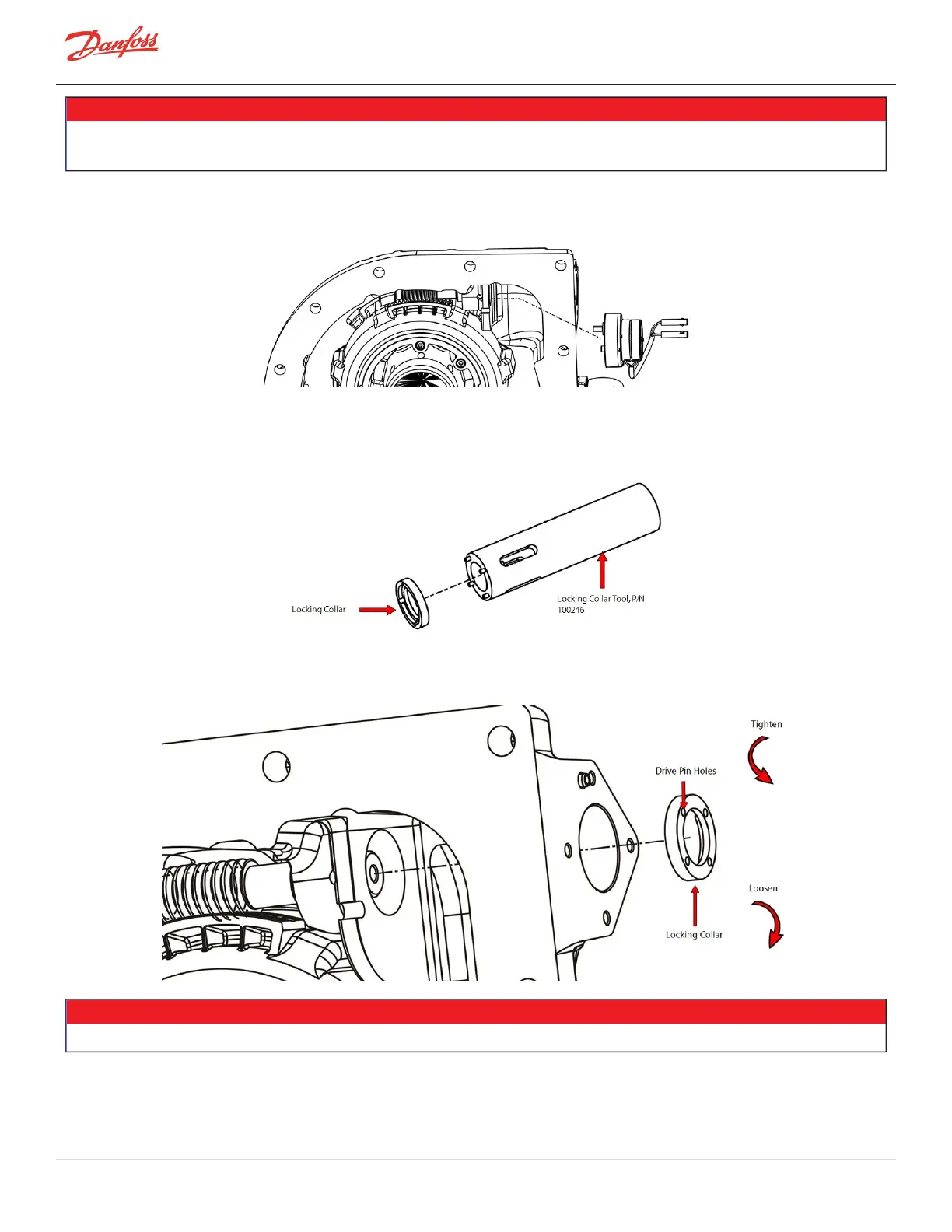
Figure 4-56 IGV Motor Assembly Removal
7. SlidetheLockingCollarTool(P/N100246)intothehousingandoverthewormshaft.Ensurethedrive
pinsareengagedintheLockingCollar.RefertoFigure4-57LockingCollarTool.
Figure 4-57 Locking Collar Tool
8. TurntheLockingCollarclockwisetoremove.RefertoFigure4-58LockingCollar.
Figure 4-58 Locking Collar
NOTE
TheLockingCollarcontainsaleft-handthread.Toremove,turnclockwisewhenviewingfromthemotorend.
9. RemovethewormgearbyrotatingtheIGVThroatclockwisebyhandorrotatethewormshaftbyhand.
RefertoFigure4-59WormGearRemovalonpage89.
Page 88 of 294 - M-SV-001-EN Rev. H 1/23/2023