Connection examples
Setup change
-
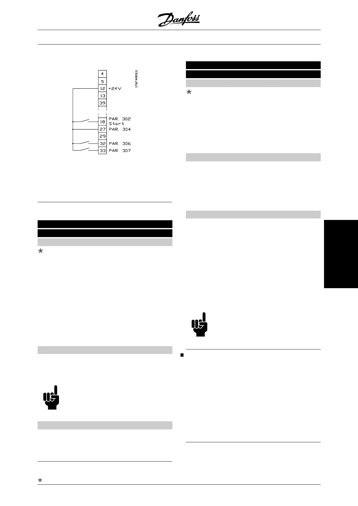
Selection of Setup using terminals 32 and 33.
Parameter 306 = Selection of Setup, lsb [4]
Parameter 307 = Selection of Setup, msb [4]
Parameter 002 =MultiSetup [5].
003 Copying of Setups
(SETUP COPY)
Value:
No copying (NO COPY) [0]
Copy active Setup to Setup 1
(COPY TO SETUP 1) [1]
Copy active Setup to Setup 2
(COPY TO SETUP 2) [2]
Copy active Setup to Setup 3
(COPY TO SETUP 3) [3]
Copy active Setup to Setup 4 (COPY TO SET-
UP 4) [4]
Copy active Setup to all
(COPY TO ALL) [5]
Function:
A copy is made from the active Setup selected in pa-
rameter 002 Active Setup to the Setup or Setups se-
lected in parameter 003 Copying of Setups.
NB!
Copying is only possible in Stop mode
(motor stopped on a Stop command).
Description of choice:
The copying starts when the required copying function
has been selected and the [OK] key has been pressed.
The display indicates when copying is in progress.
004 LCP copy
(LCP COPY)
Value:
No copying (NO COPY) [0]
Upload all parameters
(UPLOAD ALL PARAMET.) [1]
Download all parameters
(DOWNLOAD ALL PARAM.) [2]
Download power-independent par.
(DOWNLOAD SIZE INDEP.) [3]
Function:
Parameter 004 LCP copy is used if the integrated
copying function of the control panel is to be used.
This function is used if all parameter Setups are to be
copied from one frequency converter to another by
moving the control panel.
Description of choice:
Select Upload all parameters [1] if all parameter values
are to be transmitted to the control panel.
Select Download all parameters [2] if all transmitted
parameter values are to be copied to the frequency
converter on which the control panel has been moun-
ted.
Select Download power-independent par. [3] if only the
power-independent parameters are to be downloaded.
This is used if downloading to a frequency converter
that has a different rated power than the one from
where the parameter Setup originates.
NB!
Uploading/Downloading can only be car-
ried out in the Stop mode.
Setup of user-defined readout
Parameter 005 Max. value of user-defined readout and
006 Unit for user-defined readout allow users to design
their own readout which can be seen if user-defined
readout has been selected under display readout. The
range is set in parameter 005 Max. value of user-de-
fined readout and the unit is determined in parameter
006 Unit for user-defined readout. The choice of unit
decides whether the ratio between the output frequen-
cy and the readout is a linear, square or cubed ratio.
VLT
®
6000 HVAC Series
= factory setting, () = display text, [] = value for use in communication via serial communication port
MG.61.B5.02 - VLT
®
is a registered Danfoss trademark 101
Programming

 Loading...


