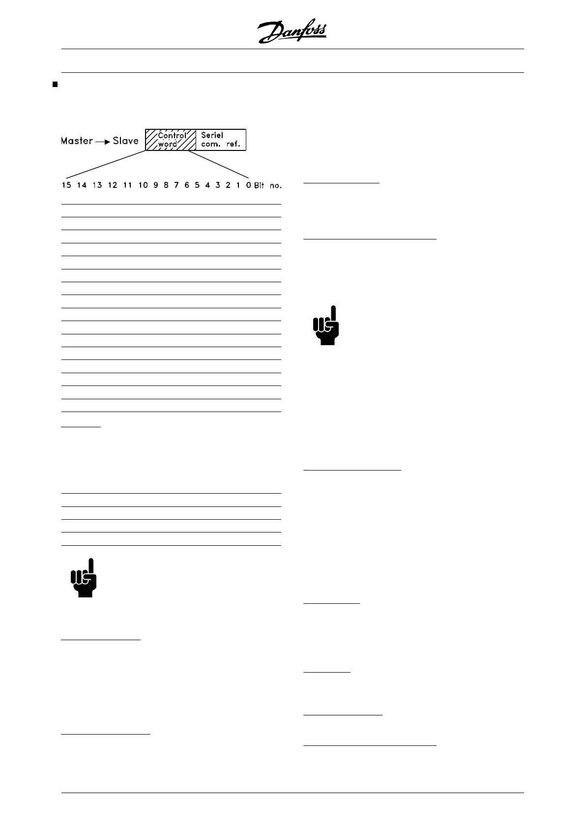
Control word according to FC protocol
The control word is used for transmitting commands
from a master (e.g. a PC) to a slave.
Bit Bit = 0 Bit =1
00 Preset ref. lsb
01 Preset ref. msb
02 DC braking
03 Coasting stop
04 Quick stop
05 Freeze output frequency
06
Ramp stop Start
07 Reset
08 Jog
09 No function No function
10 Data not valid Data valid
11 Activate relay 1
12 Activate relay 2
13 Choice of setup lsb
14 Choice of setup msb
15 Reversing
Bit 00/01:
Bits 00 and 01 are used for choosing between the four
pre-programmed references (parameters 211- 214
Preset reference) in accordance with the following ta-
ble:
Preset ref.
Parameter Bit 01 Bit 00
1 211 0 0
2 212 0 1
3 213 1 0
4 214 1 1
NB!
Parameter 508 Choice of preset refer-
ence is used to choose how bits 00/01 are
to be gated with the corresponding func-
tions of the digital inputs.
Bit 02, DC BRAKE:
Bit 02 = 0 leads to DC braking and stop. Set braking
current and duration in parameter 114 DC braking cur-
rent and in parameter 115 DC braking time. Note:
Parameter 504 DC brake is used for selecting how bit
02 is to be gated with the corresponding function of
terminal 27.
Bit 03, Coasting stop:
Bit 03 = "0" means that the frequency converter im-
mediately "lets go" of the motor (the output transistors
are "turned off"), which means that the motor runs
freely until it stops.
Bit 03 = "1" means that the frequency converter is able
to start the motor, provided the other conditions for
starting are fulfilled. Note: In parameter 503 Coasting
stop the choice is made of how bit 03 is to be gated
with the corresponding function of terminal 27.
Bit 04, Quick stop:
Bit 04 = "0" leads to a stop in which the motor speed
is ramped down to stop via parameter 207 Ramp-down
time.
Bit 05, Freeze output frequency:
Bit 05 = "0" means that the given output frequency (in
Hz) is frozen. The frozen output frequency can now
only be changed via the digital inputs programmed for
Speed up and Speed down.
NB!
If Freeze output is active, the frequency
converter cannot be stopped via Bit 06
Start or via terminal 18. The frequency
converter can only be stopped in the fol-
lowing ways:
•
Bit 03 Coasting stop
• Terminal 27
•
Bit 02 DC braking
•
Terminal 19 programmed for DC braking
Bit 06, Ramp stop/start:
wBit 04 = "0" leads to a stop in which the motor speed
is ramped down to stop via parameter 207 Ramp-down
time.
Bit 06 = "1" means that the frequency converter is able
to start the motor, provided the other conditions for
starting are fulfilled. Note: In parameter 505 Start a
choice is made of the way bit 06 Ramp stop/start is to
be gated with the corresponding function of terminal
18.
Bit 07, Reset:
Bit 07 = "0" leads to no reset.
Bit 07 = "1"means that a trip is reset.
Reset is activated on the leading edge of the signal,
i.e. at the change from logic '0' to logic '1'.
Bit 08, Jog:
Bit 08 = "1" means that the output frequency is deter-
mined by parameter 209 Jog frequency.
Bit 09, No function:
Bit 09 has no function.
Bit 10, Data not valid/Data valid:
VLT
®
6000 HVAC Series
162 MG.61.B5.02 - VLT
®
is a registered Danfoss trademark

 Loading...


