Electrical installation, control cables
Torque: 0.5-0.6 Nm
Screw size: M3
Generally speaking, control cables must be screened/
armoured and the screen must be connected by
means of a cable clamp at both ends to the metal cab-
inet of the unit (see Earthing of screened/ armoured
control cables). Normally, the screen must also be con-
nected to the body of the controlling unit (follow the
instructions for installation given for the unit in ques-
tion).
If very long control cables are used, 50/60 Hz earth
loops may occur that will disturb the whole system.
This problem can be solved by connecting one end of
the screen to earth via a 100nF condenser (keeping
leads short).
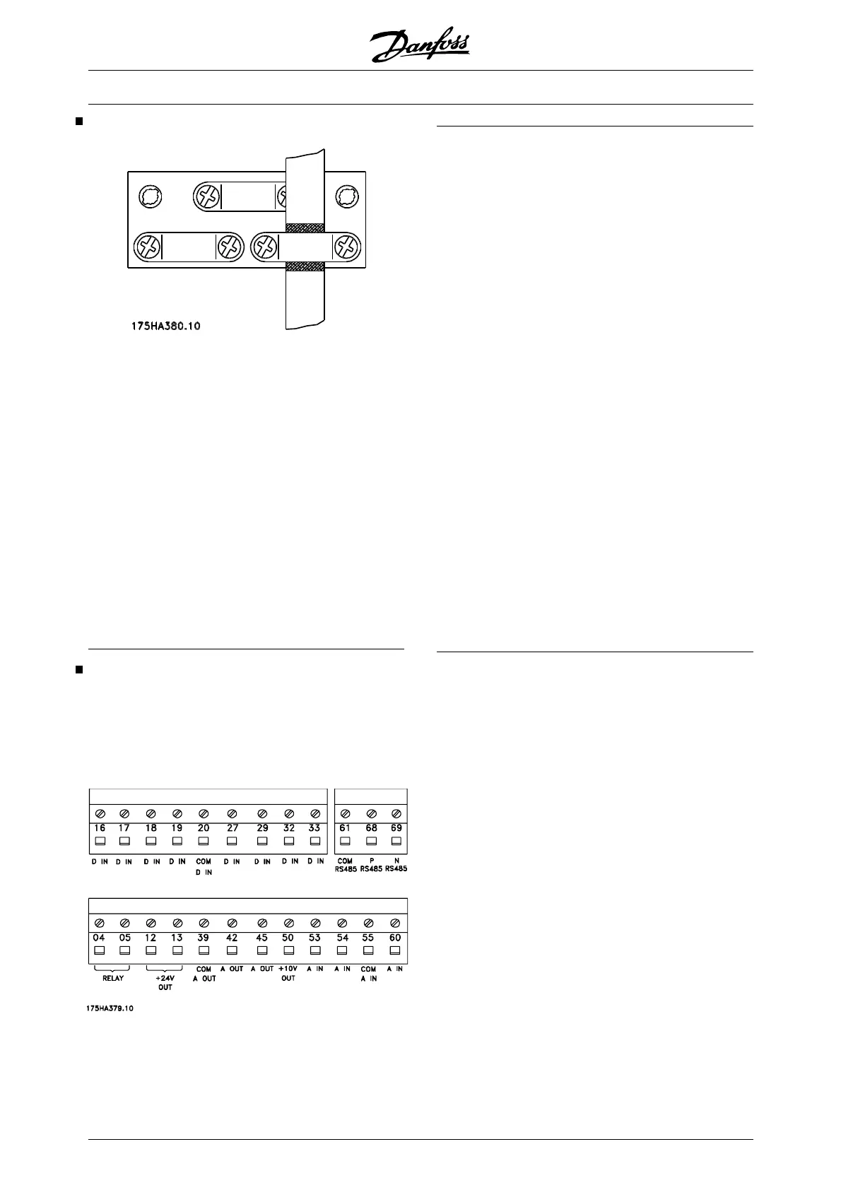
Electrical installation, control cables
Max. control cable cross section: 1.5 mm
2
/16 AWG
Torque: 0.5-0.6 Nm
Screw size: M3
See Earthing of screened/armoured control cables for
correct termination of control cables.
No. Function
04, 05 Relay output 2 can be used for indicating sta-
tus and warnings.
12, 13 Voltage supply to digital inputs. For the 24 V
DC to be used for digital inputs, switch 4 on the
control card must be closed, position "on".
16-33
Digital inputs. See parameters 300-307 Digital
inputs.
20 Ground for digital inputs.
39 Ground for analogue/digital outputs. Must be
connnected to terminal 55 by means of a three-
wire transmitter. See Examples of connection.
42, 45 Analogue/digital outputs for indicating frequen-
cy, reference, current and torque. See param-
eters 319-322 Analogue/digital outputs.
50 Supply voltage to potentiometer and thermis-
tor 10 V DC.
53, 54 Analogue voltage input, 0 - 10 V DC.
55 Ground for analogue voltage inputs.
60 Analogue current input 0/4-20 mA. See pa-
rameters 314-316 Terminal 60.
61
Termination of serial communication. See
Earthing of screened/armoured control cables.
This terminal is not normally to be used.
68, 69 RS 485 interface, serial communication.
Where the frequency converter is connected to
a bus, switches 2 and 3 (switches 1- 4 - see
next page) must be closed on the first and the
last frequency converter. On the remaining fre-
quency converters, switches 2 and 3 must be
open. The factory setting is closed (position
on).
VLT
®
6000 HVAC Series
88 MG.61.B5.02 - VLT
®
is a registered Danfoss trademark

 Loading...


