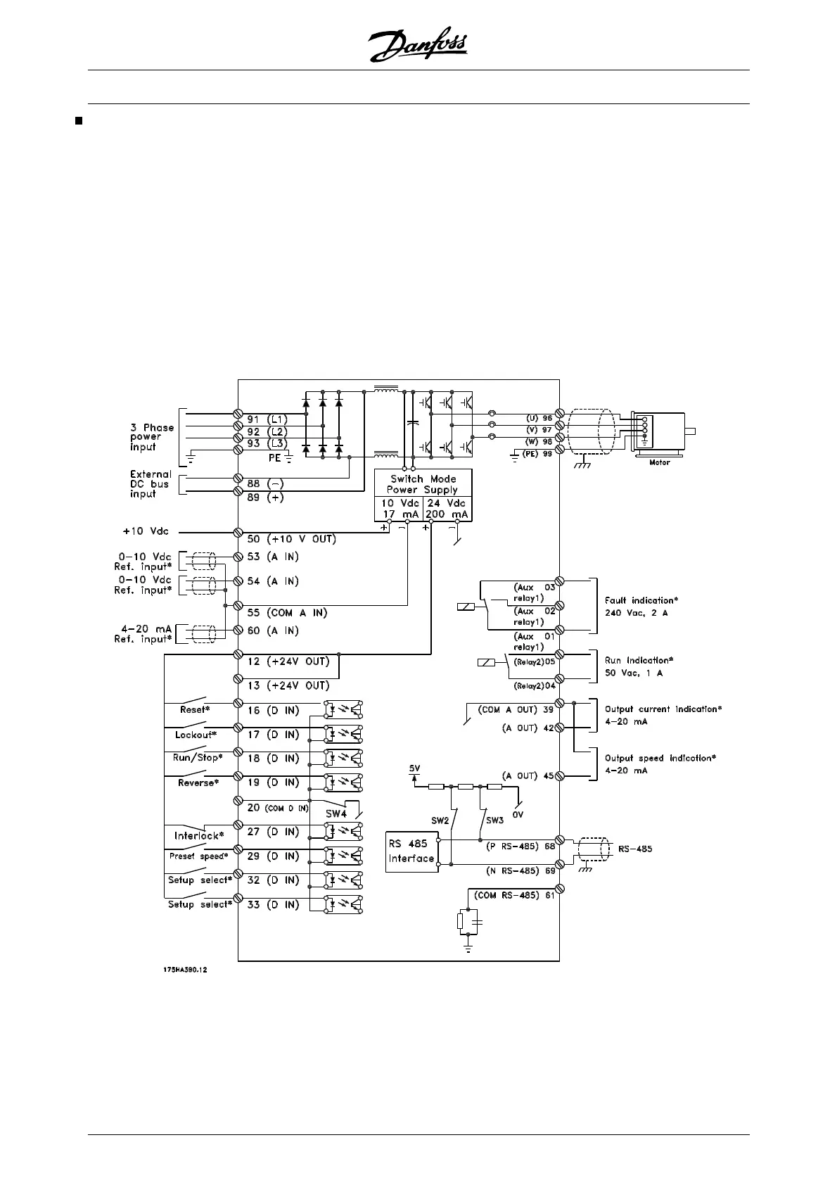
Connection examples, VLT 6000 HVAC
The diagram below gives an example of a typical VLT
6000 HVAC installation.
The mains supply is connected to terminals 91 (L1),
92 (L2) and 93 (L3), while the motor is connected to
96 (U), 97 (V) and 98 (W). These numbers can also be
seen from the terminals of the frequency converter.
An external DC supply or a 12-pulse option can be
connected to terminals 88 and 89. Please ask Danfoss
for a Design Guide to learn more.
Analogue inputs can be connected to terminals 53 [V],
54 [V] and 60 [mA]. These inputs can be programmed
for either reference, feedback or thermistor. See An-
alogue inputs in parameter group 300.
There are 8 digital inputs, which can be connected to
terminals 16-19, 27, 29, 32, 33. These inputs can be
programmed in accordance with the table in Inputs and
outputs 300-328.
There are two analogue/digital outputs (terminals 42
and 45), which can be programmed to show the
present status or a process value, such as 0-f
MAX
. Re-
lay outputs 1 and 2 can be used for giving the present
status or a warning.
On terminals 68 (P+) and 69 (N-) RS 485 interface, the
frequency converter can be controlled and monitored
via serial communication.
VLT
®
6000 HVAC Series
90 MG.61.B5.02 - VLT
®
is a registered Danfoss trademark

 Loading...


