Tightening-up torque and screw sizes
The table shows the torque required when fitting ter-
minals to the frequency converter. For VLT
6002-6032, 200-240 V, VLT 6002-6122, 380-460 and
VLT 6002-6072 525-600 V the cables must be fas-
tened with screws. For VLT 6042-6062, 200-240 V and
for VLT 6152-6550, 380-460 V and VLT 6102-6652,
525-600 V the cables must be fastened with bolts.
These figures apply to the following terminals:
91, 92, 93
Mains terminals (Nos.) L1, L2, L3
96, 97, 98
Motor terminals (Nos.) U, V, W
Earth terminal (Nos.) 94, 95, 99
VLT type
3 x 200 - 240 V
Tightening-up
torque
Screw/bolt
size
Tool
VLT 6002-6005 0.5-0.6 Nm M3
VLT 6006-6011 1.8 Nm (IP 20) M4
VLT 6006-6016 1.8 Nm (IP 54) M4
VLT 6016-6027 3.0 Nm (IP 20)
M5
3)
4 mm
VLT 6022-6027
3.0 Nm (IP 54)
2)
M5
3)
4 mm
VLT 6032 6.0 Nm
M6
3)
5 mm
VLT 6042-6062 11.3 Nm M8 (bolt)
VLT type
3 x 380-460 V
Tightening-up
torque
Screw/bolt
size
Tool
VLT 6002-6011 0.5-0.6 Nm M3
VLT 6016-6027 1.8 Nm (IP 20) M4
VLT 6016-6032 1.8 Nm (IP 54) M4
VLT 6032-6052 3.0 Nm (IP 20)
M5
3)
4 mm
VLT 6042-6052
3.0 Nm (IP 54)
2)
M5
3)
4 mm
VLT 6062-6072 6.0 Nm
M6
3)
5 mm
VLT 6102-6122 15 Nm (IP 20)
M8
3)
6 mm
24 Nm (IP 54)
1) 3)
8 mm
VLT 6152-6352
19 Nm
4)
M10 (bolt)
5)
16 mm
VLT 6402-6602 19 Nm M10 (com-
pression lug)
5)
16 mm
9.5 Nm
M8 (box lug)
5)
13 mm
VLT type
3 x 525-600 V
Tightening-up
torque
Screw/bolt
size
Tool
VLT 6002-6011 0.5-0.6 Nm M3
VLT 6016-6027 1.8 Nm M4
VLT 6032-6042
3.0 Nm
2)
M5
3)
4 mm
VLT 6052-6072 6.0 Nm
M6
3)
5 mm
VLT 6102-6402
19 Nm
4)
M10 (bolt)
5)
16 mm
VLT 6502-6652 19 Nm M10 (com-
pression lug)
5)
16 mm
9.5 Nm
M8 (box lug)
5)
13 mm
1. Loadsharing terminals 14 Nm/M6, 5 mm Allen key
2. IP 54 units with RFI filter line terminals 6 Nm
3. Allen screws (hexagon)
4. Loadsharing terminals 9.5 Nm/M8 (bolt)
5. Wrench
Mains connection
Mains must be connected to terminals 91, 92, 93.
Mains voltage 3 x 200-240 V
91, 92, 93 Mains voltage 3 x 380-460 V
L1, L2, L3 Mains voltage 3 x 525-600 V
NB!
Check that the mains voltage fits the
mains voltage of the frequency converter,
which can be seen from the nameplate.
See Technical data for correct sizing of cable cross-
sections.
Motor connection
The motor must be connected to terminals 96, 97, 98.
Earth to terminal 94/95/99.
Nos.
96. 97. 98
U, V, W
Motor voltage 0-100 % of mains voltage
No. 94/95/99 Earth connection
See Technical data for correct sizing of cable cross-
sections.
All types of three-phase asynchronous standard mo-
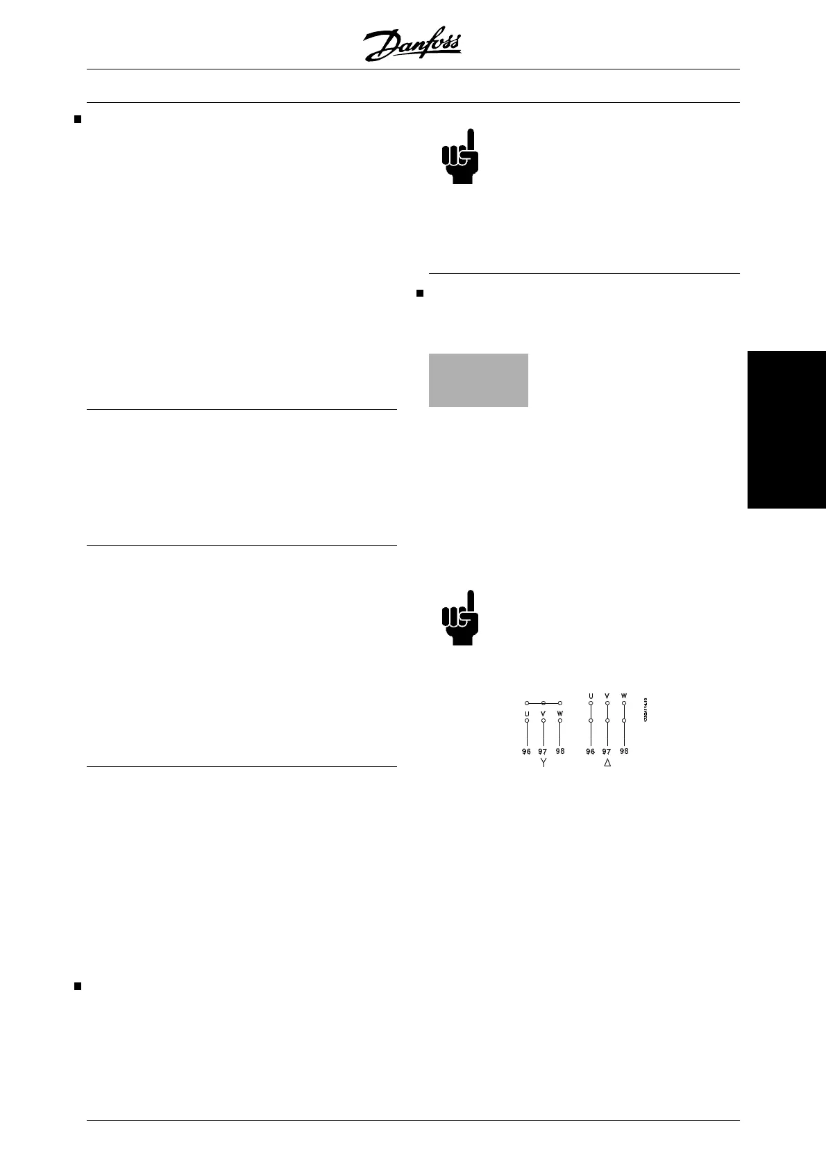
tors can be used with a VLT 6000 HVAC unit.
Small-size motors are normally star-connected.
(220/380 V, ∆/Y). Large-size motors are delta-connec-
ted (380/660 V, ∆/Y). The correct connection and volt-
age can be read from the motor nameplate.
NB!
In older motors without phase coil insula-
tion, a LC filter should be fitted to the
frequency converter output. See the De-
sign Guide or contact Danfoss.
VLT
®
6000 HVAC Series
MG.61.B5.02 - VLT
®
is a registered Danfoss trademark 85
Installation

 Loading...


