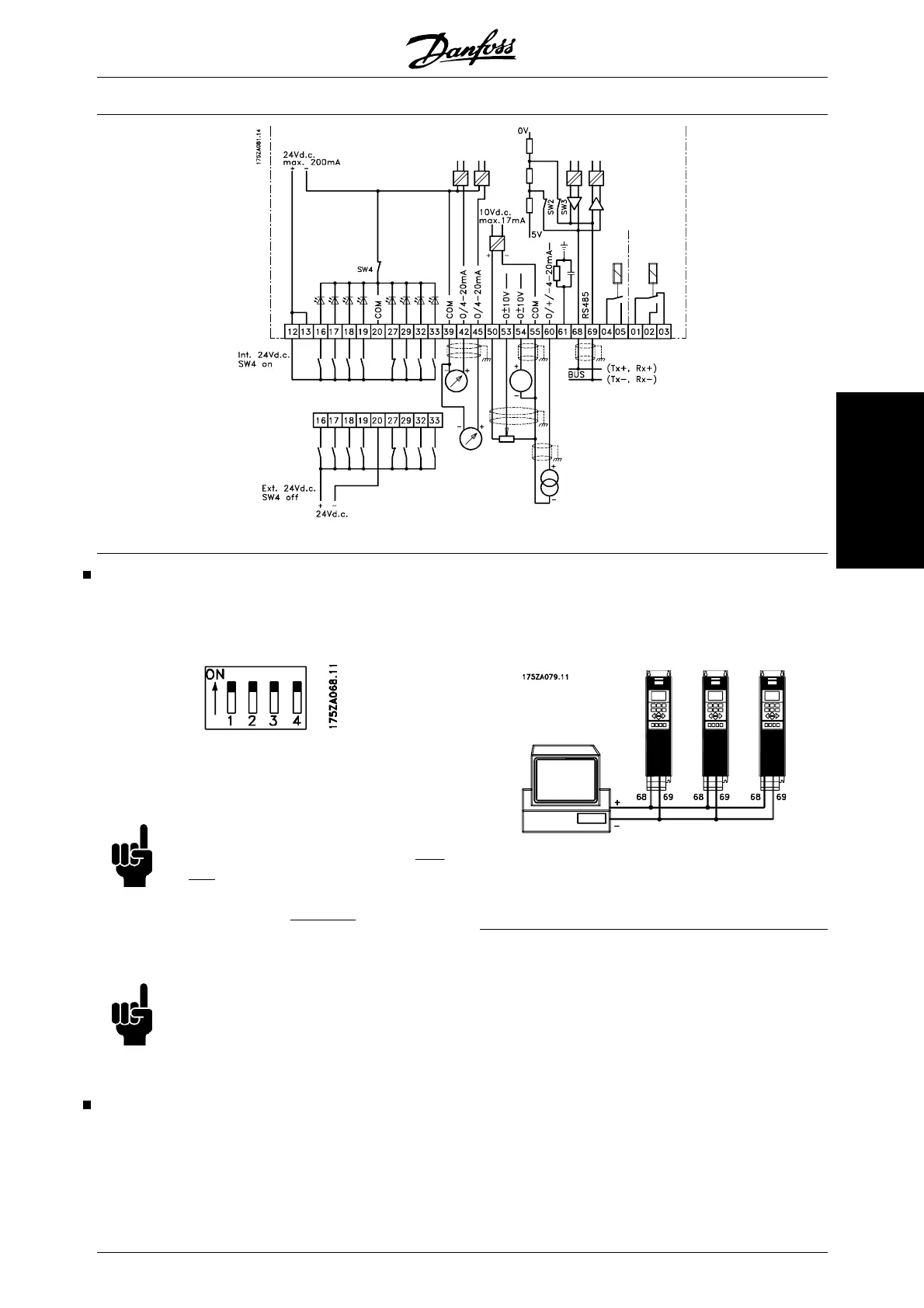
Switches 1-4
The dipswitch is located on the control card. It is used
for serial communication and external DC supply.
The switching position shown is the factory setting.
Switch 1 has no function.
Switches 2 and 3 are used for terminating an RS-485
interface to the serial communication bus
NB!
When the frequency converter is the
first
or
last device on the serial communication
bus, switches 2 and 3 must be ON in that
designated VLT.
Any other VLTs on the
serial communication bus must have
switches 2 and 3 set to OFF.
NB!
Please note that when Switch 4 is in po-
sition "OFF," the external 24 V DC supply
is galvanically isolated from the frequency
converter.
Bus connection
The serial bus connection in accordance with the RS
485 (2-conductor) norm is connected to terminals
68/69 of the frequency converter (signals P and N).
Signal P is the positive potential (TX+,RX+), while sig-
nal N is the negative potential (TX-,RX-).
If more than one frequency converter is to be connec-
ted to a given master, use parallel connections.
In order to avoid potential equalizing currents in the
screen, the cable screen can be earthed via terminal
61, which is connected to the frame via an RC-link.
VLT
®
6000 HVAC Series
MG.61.B5.02 - VLT
®
is a registered Danfoss trademark 89
Installation

 Loading...


