[RESET] is used for resetting the fre-
quency converter after an alarm (trip).
Can be selected as Enable [1] or Disable
[0] via parameter 015 Reset on LCP.
See also List of warnings and alarms.
Display mode
In normal operation, any 4 different operating variables
can be indicated continuously: 1.1 and 1.2 and 1.3 and
2. The present operating status or alarms and warn-
ings that have arisen are shown in line 2 in the form of
a number. In the case of alarms, the alarm in question
will be shown in lines 3 and 4, accompanied by an ex-
planatory note. Warnings will flash in line 2, with an
explanatory note in line 1. In addition, the display
shows the active Setup.
The arrow indicates the direction of rotation; here the
frequency converter has an active reversing signal.
The arrow body disappears if a stop command is given
or if the output frequency falls below 0.01 Hz. The bot-
tom line gives the status of the frequency converter.
The scroll list on the next page gives the operating data
that can be shown for variable 2 in display mode.
Changes are made via the [+/-] keys.
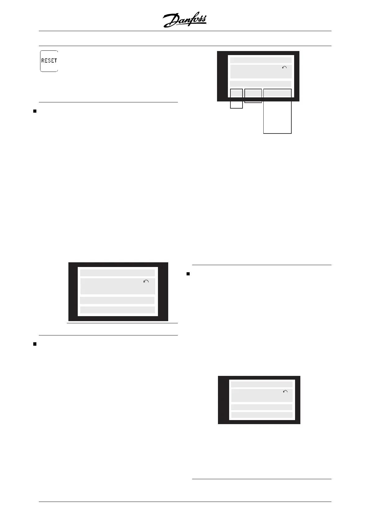
1st line
195NA113.10
VAR 2
SETUP
1
STATUS
VAR 1.1 VAR 1.2 VAR 1.3
2nd line
3rd line
4th line
Display mode, cont.
Three operating data values can be shown in the first
display line, while one operating variable can be
shown in the second display line. To be programmed
via parameters 007, 008, 009 and 010 Display read-
out.
• Status line (4th line):
175ZA701.10
40.0Hz
80.0% 5.08A 2.15kW
SETUP
1
AUTO REMOTE RUNNING
HAND LOCAL STOP
LOCAL STOPRAMPING
HAND JOGGING
.
.
.
.
STAND BY
OFF
The left part of the status line indicates the control ele-
ment of the frequency converter that is active. AUTO
means that control is via the control terminals, while
HAND indicates that control is via the local keys on the
control unit.
OFF means that the frequency converter ignores all
control commands and stops the motor.
The centre part of the status line indicates the refe-
rence element that is active. REMOTE means that the
reference from the control terminals is active, while
LOCAL indicates that the reference is determined via
the [+/-] keys on the control panel.
The last part of the status line indicates the current
status, for example "Running", "Stop" or "Alarm".
Display mode I:
VLT 6000 HVAC offers different display modes de-
pending on the mode selected for the frequency con-
verter. The figure on the next page shows the way to
navigate between different display modes.
Below is a display mode, in which the frequency con-
verter is in Auto mode with remote reference at an
output frequency of 40 Hz.
In this display mode, reference and control are deter-
mined via the control terminals.
The text in line 1 gives the operating variable shown in
line 2.
175ZA683.10
SETUP
1
FREQUENCY
40.0Hz
AUTO REMOTE RUNNING
Line 2 gives the current output frequency and the ac-
tive Setup.
Line 4 says that the frequency converter is in Auto
mode with remote reference, and that the mo tor is
running.
VLT
®
6000 HVAC Series
94 MG.61.B5.02 - VLT
®
is a registered Danfoss trademark

 Loading...


