Inputs and outputs 300-365
In this parameter group, the functions that relate to the
input and output terminals of the frequency converter
are defined.
The digital inputs (terminals 16, 17, 18, 19, 27, 29, 32
and 33) are programmed in parameters 300-307. The
table below gives the options for programming the in-
puts. The digital inputs require a signal of 0 or 24 V DC.
A signal lower than 5 V DC is a logic ‘0’, while a signal
higher than 10 V DC is a logic ‘1’.
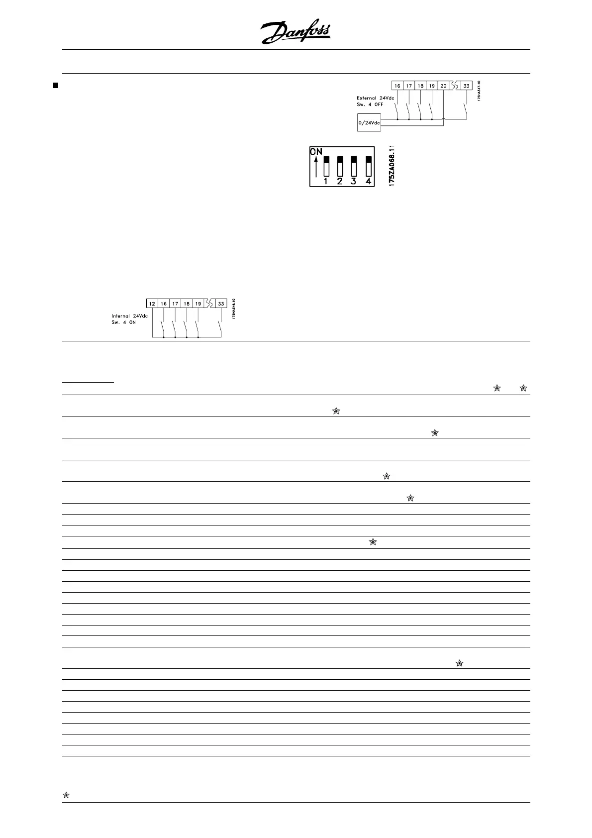
The terminals for the digital inputs can be connected
to the internal 24 V DC supply, or an external 24 V DC
supply can be connected.
The drawings in the next column show one Setup us-
ing the internal 24 V DC supply and one Setup using
an external 24 V DC supply.
Switch 4, which is located on the
Dip switch control card, is used
for separating the common po-
tential of the internal 24 V DC
supply from
the common potential of the external 24 V DC supply.
See Electrical installation.
Please note that when Switch 4 is in the OFF position,
the external 24 V DC supply is galvanically isolated
from the frequency converter.
Digital inputs Terminal no. 16 17 18 19 27 29 32 33
parameter 300 301 302 303 304 305 306 307
Value:
No function (NO OPERATION) [0] [0] [0] [0] [0]
[0] [0]
Reset (RESET) [1][1] [1] [1] [1]
Coasting stop, inverse (COAST INVERSE) [0]
Reset and coasting stop, in-
verse
(COAST & RESET INVERS) [1]
Start (START) [1]
Reversing (REVERSE) [1]
Reversing and start (START REVERSE) [2]
DC-braking, inverse (DC BRAKE INVERSE) [3] [2]
Safety Interlock (SAFETY INTERLOCK) [3]
Freeze Reference (FREEZE REFERENCE) [2]
[2]
[2] [2] [2]
Freeze output (FREEZE OUTPUT) [3] [3] [3] [3] [3]
Selection of Setup, Isb (SETUP SELECT LSB) [4] [4] [4]
Selection of Setup, msb (SETUP SELECT MSB) [4] [5] [4]
Preset reference, on (PRESET REF. ON) [5] [5] [6] [5] [5]
Preset reference, lsb (PRESET REF. SEL. LSB) [6] [7] [6]
Preset reference, msb (PRESET REF. MSB) [6] [8] [6]
Speed down (SPEED DOWN) [7] [9] [7]
Speed up (SPEED UP) [7] [10] [7]
Run permissive (RUN PERMISSIVE) [8] [8] [11] [8] [8]
Jog (JOG) [9] [9] [12] [9] [9]
Data change lock (PROGRAMMING LOCK) [10] [10] [13] [10] [10]
Pulse reference (PULE REFERENCE) [11] [14]
Pulse feedback (PULSE FEEDBACK) [11]
Hand start (HAND START) [11] [12] [15] [11] [12]
Auto start (AUTOSTART) [12] [13] [16] [12] [13]
Fire mode (FIRE MODE) [13] [14]
Fire mode inverse (FIRE MODE INVERSE) [14] [15]
Enable RTC (ENABLE RTC) [25] [25]
VLT
®
6000 HVAC Series
= factory setting, () = display text, [] = value for use in communication via serial communication port
124 MG.61.B5.02 - VLT
®
is a registered Danfoss trademark

 Loading...


