3 Basic Operating Principle of the AHF
3.1 Operating Principle
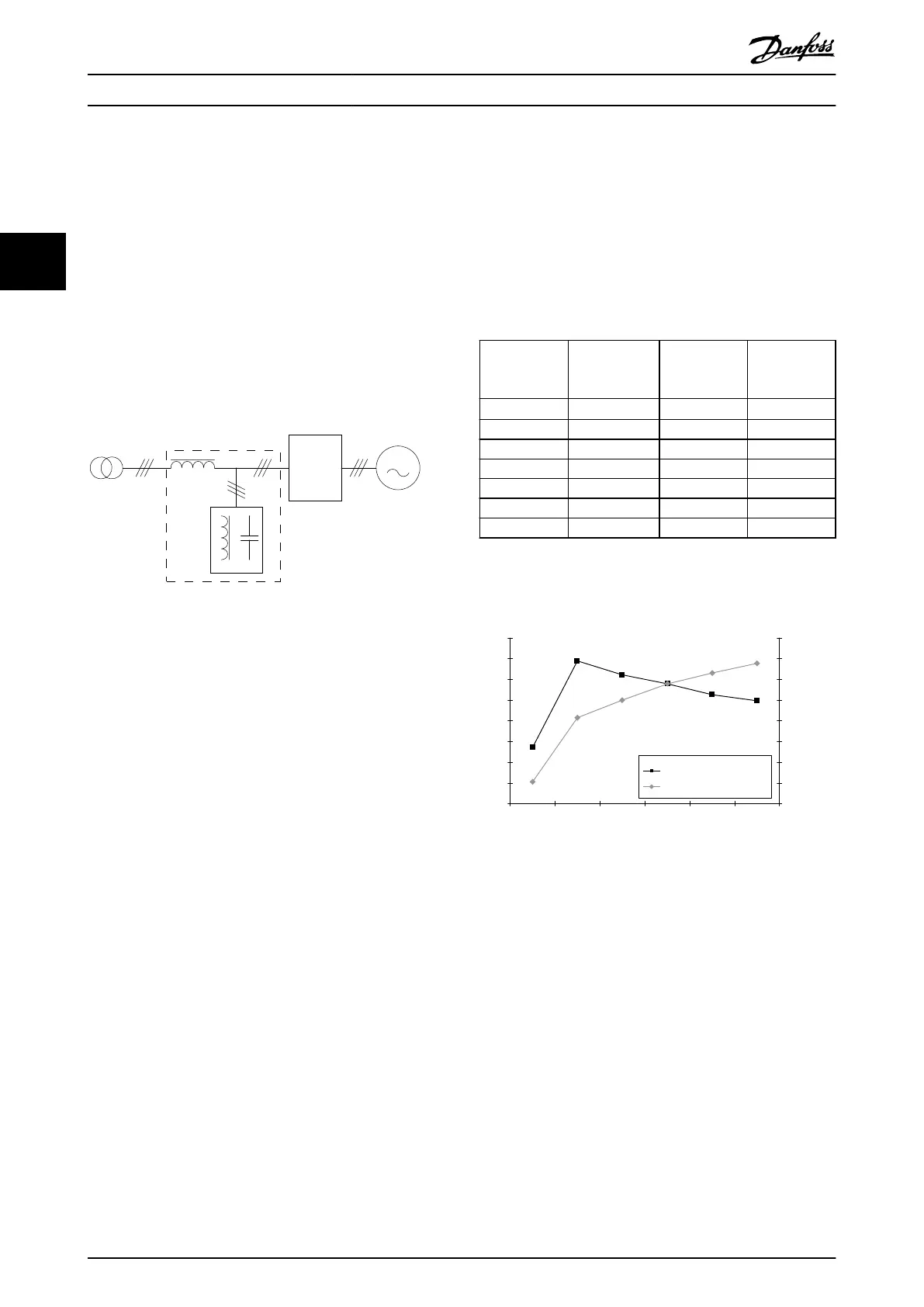
The VLT
®
Advanced Harmonic Filter AHF 005/AHF 010
consists of a main inductor L
0
and a 2-stage absorption
circuit with the inductors L
1
and L
2
, and the capacitors C
1
and C
2
. The absorption circuit is specially tuned to
eliminate harmonics starting with the 5
th
harmonic and is
specic for the designed supply frequency. Therefore, the
circuit for 50 Hz has dierent parameters than the circuit
for 60 Hz.
130BB578.11
Frequency
converter
Illustration 3.1 Operating Principle
AHFs are available in 2 variants for 2 performance levels:
•
AHF 005 with 5% THDi.
•
AHF 010 with 10% THDi.
Each of the 2 variants is available with the following
voltages:
•
380–415 V, 50 Hz.
•
380–415 V, 60 Hz.
•
440–480 V, 60 Hz.
•
600 V, 60 Hz.
•
500–690 V, 50 Hz.
The AHF 010 oers a performance similar to 12-pulse
rectiers, and the AHF 005 oers a performance similar to
18-pulse rectiers.
The lter performance in terms of THDi varies as a function
of the load. At nominal load, the lter performance is
better than 10% THDi for AHF 010 and 5% THDi for AHF
005.
At part load, the THDi has higher values. However, the
absolute value of the harmonic current is lower at part
loads, even if the THDi has a higher value. Therefore, the
negative eect of the harmonics at part loads is lower than
at full load.
Example of part load
An 18.5 kW (25 hp) frequency converter is installed on a
400 V/50 Hz grid with a 34 A AHF 010 (type code AHF-
DA-34-400-50-20-A).
The values in Table 3.1 are measured for dierent load
currents, using a harmonic analyzer:
I
line
RMS Basic current
at 50 Hz I
1)
RMS
THDi Total
harmonic
current I
h
RMS
[A] [A] [%]
[A]
1)
9.6 9.59 5.45 0.52
15.24 15.09 13.78 2.07
20.24 20.08 12.46 2.5
25.17 25 11.56 2.89
30.27 30.1 10.5 3.15
34.2 34.03 9.95 3.39
Table 3.1 Example of Load Currents
1) The total harmonic current has been calculated. The THDi versus
load plot is shown in Illustration 3.2.
AHF-DA-34-400-50-20-A
0
2
4
6
8
10
12
14
16
10 15 20 25 30 35
I
line
[A]
THDi [%]
0
0.5
1
1.5
2
2.5
3
3.5
4
Harmonic current I
h
[A]
THDi [%]
Harmonic current I
h
[A]
130BB579.11
Illustration 3.2 THDi versus Load
At part load, 15 A, the THDi is approximately 14%
compared to 10% at the nominal load of 34 A. At the
same time, the total harmonic current is only 2.07 A at
15 A line current against 3.39 A harmonic current at 34 A
line current. Thus, THDi is only a relative indicator of the
harmonic performance. The harmonic distortion of the
voltage is less at part load than at nominal load.
Background distortion
Factors such as background distortion and grid unbalance
can aect the performance of AHF lters. The specic
gures are dierent from lter to lter, and Illustration 3.3
to Illustration 3.6 show typical performance characteristics.
For specic details, use a harmonic design tool such as
MCT 31 or Harmonic Calculation Software (HCS).
The design of the lters aims to achieve 10%, respectively,
5% THDi levels with a background distortion of THDv =
2%. Practical measurements on typical grid conditions in
Basic Operating Principle o...
VLT
®
Advanced Harmonic Filter AHF 005/AHF 010
14 Danfoss A/S © 10/2016 All rights reserved. MG80C502
33