frequency converter installations often show that the
performance of the lter is slightly better with a 2%
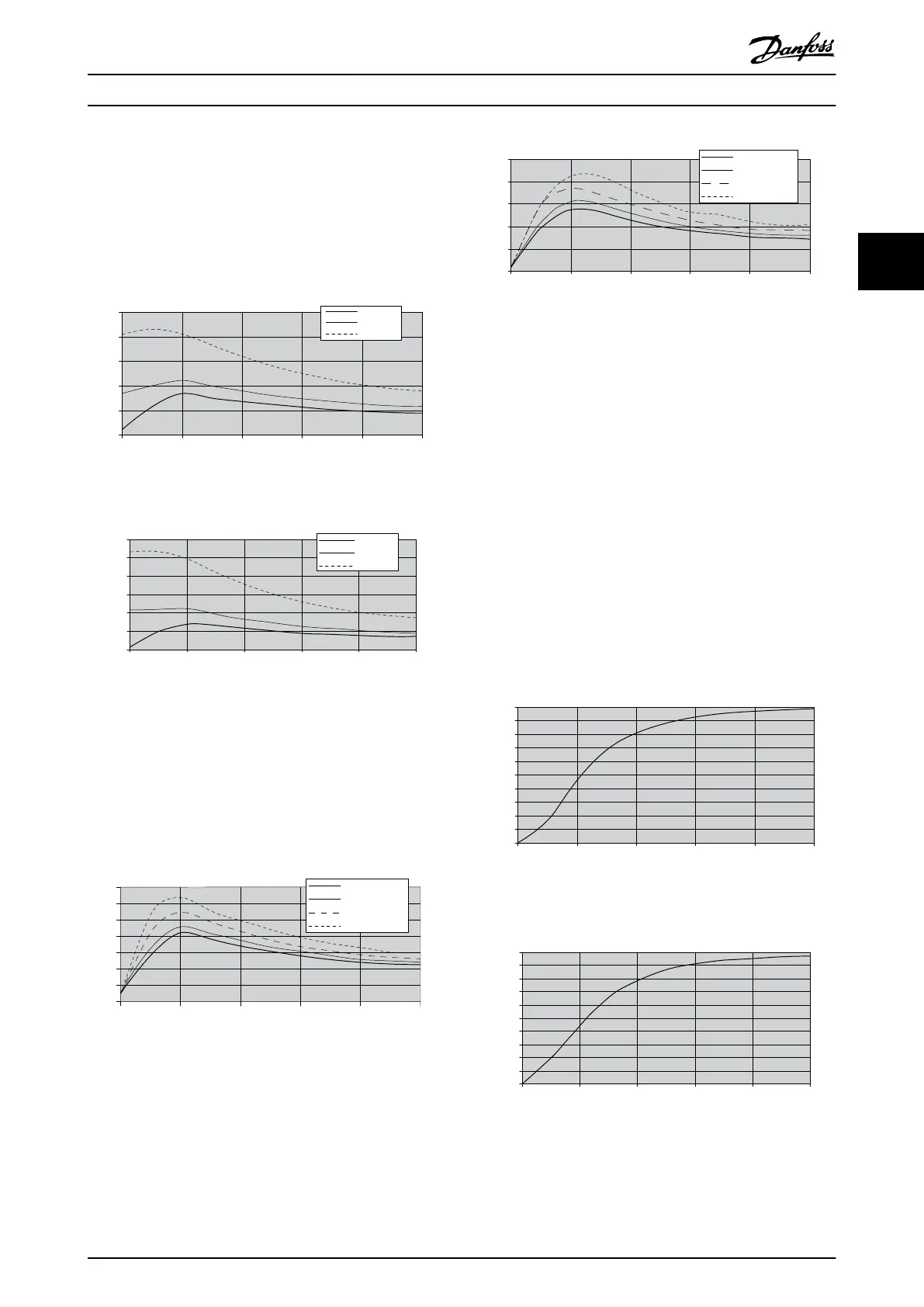
background distortion. However, the complexity of the grid
conditions and the mix of specic harmonics does not
provide a general rule about the performance on a
distorted grid. Illustration 3.3 and Illustration 3.4 show
worst-case performance deterioration characteristics with
the background distortion.
0 20 40 60 80 100
0
5
10
15
20
25
THvD 0%
THvD 2%
THvD 5%
Load [%]
THiD average [%]
130BB580.10
Illustration 3.3 AHF 005
0
10
20
30
40
50
60
0 20 40 60 80 100
Load [%]
THvD 0%
THvD 2%
THvD 5%
THiD [%]
130BB581.10
Illustration 3.4 AHF 010
Performance at 10% THDv has not been plotted. However,
the lters have been tested and can operate at 10% THDv,
but the lter performance can no longer be guaranteed.
The lter performance also deteriorates with the unbalance
of the supply. Typical performance is shown in
Illustration 3.5 and Illustration 3.6.
0% unbalance
1% unbalance
2% unbalance
3% unbalance
0 20 40 60 80 100
Load [%]
0
2
4
6
8
10
12
14
THiD [%]
130BB582.10
Illustration 3.5 AHF 005
130BB583.10
0
0 20 40 60 80 100
Load [%]
5
10
15
20
25
0% unbalance
1% unbalance
2% unbalance
3% unbalance
THiD average [%]
Illustration 3.6 AHF 010
3.1.1 Power Factor
In no-load conditions (the frequency converter is in stand-
by), the frequency converter current is negligible, and the
main current drawn from the grid is the current through
the capacitors in the harmonic lter. Therefore, the power
factor is close to 0, capacitive. The capacitive current is
approximately 25% of the lter nominal current (depends
on lter size, typical values of 20–25%). The power factor
increases with the load. Because of the higher value of the
main inductor L
0
in the VLT
®
Advanced Harmonic Filter
AHF 005, the power factor is slightly higher than in the
VLT
®
Advanced Harmonic Filter AHF 010.
Illustration 3.7 and Illustration 3.8 show typical values for
the true power factor on AHF 010 and AHF 005.
0
0,1
0,2
0,3
0,4
0,5
0,6
0,7
0,8
0,9
1
0 20 40 60 80 100
Load [%]
True Power Factor
130BB584.10
Illustration 3.7 AHF 005
0,1
0,2
0,3
0,4
0,5
0,6
0,7
0,8
0,9
1
0 20 40 60 80 100
Load [%]
0
True Power Factor
130BB585.10
Illustration 3.8 AHF 010
Basic Operating Principle o... Design Guide
MG80C502 Danfoss A/S © 10/2016 All rights reserved. 15
3 3