2 Introduction to Harmonics and Mitigation
2.1 Harmonics and Mitigation
2.1.1 Linear Loads
On a sinusoidal AC supply, a purely resistive load (for
example an incandescent light bulb) draws a sinusoidal
current in phase with the supply voltage.
The power dissipated by the load is:
P = U × I
For reactive loads (such as an asynchronous motor), the
current is no longer in phase with the voltage. Instead, the
current lags the voltage creating a lagging power factor
with a value less than 1. In the case of capacitive loads, the
current is ahead of the voltage, creating a leading power
factor with a value less than 1.
Illustration 2.1 Current Creating a True Power Factor
In this case, the AC power has 3 components:
•
Real power, (P).
•
Reactive power, (Q).
•
Apparent power, (S).
The apparent power is:
S = U × I
(where S=[kVA], P=[kW] and Q=[kVAR]).
In the case of a perfectly sinusoidal waveform, P, Q, and S
can be expressed as vectors that form a triangle:
S
2
= P
2
+ Q
2
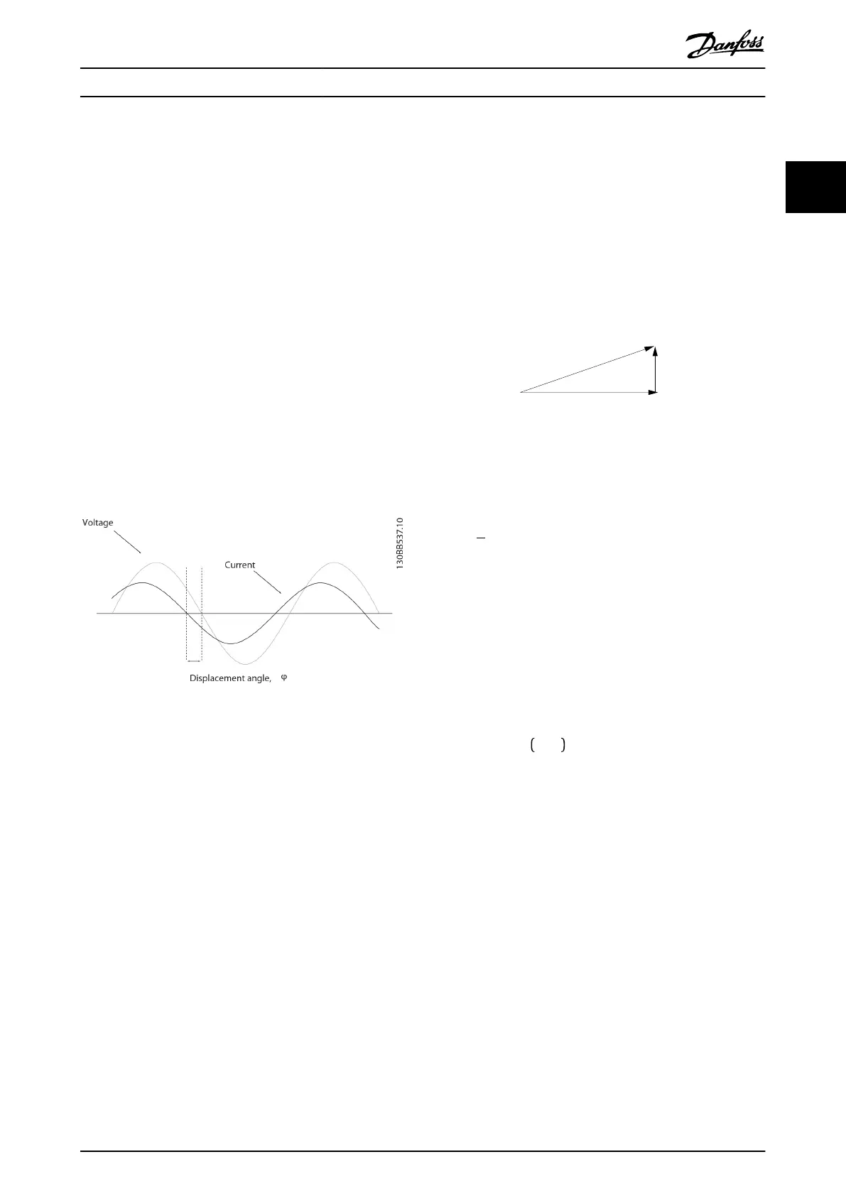
Illustration 2.2 Sinusoidal Waveform
The displacement angle between current and voltage is φ.
The displacement power factor is the ratio between the
active power (P) and apparent power (S):
DPF =
P
S
= cos(ϕ)
2.1.2 Non-linear Loads
Non-linear loads (such as diode rectiers) draw a non-
sinusoidal current. Illustration 2.3 shows the current drawn
by a 6-pulse rectier on a 3-phase supply.
A non-sinusoidal waveform can be decomposed in a sum
of sinusoidal waveforms with periods equal to integer
multiples of the fundamental waveform.
f (t) =
∑
a
h
× sin
hω
1
t
See Illustration 2.3.
Introduction to Harmonics a... Design Guide
MG80C502 Danfoss A/S © 10/2016 All rights reserved. 9
2 2