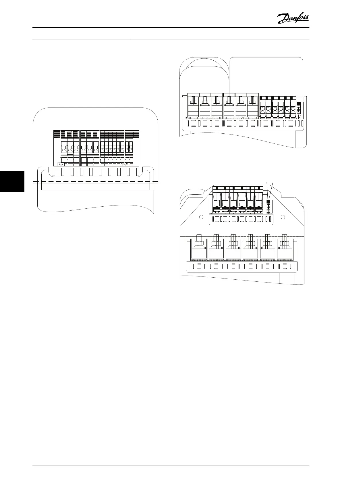
•
•
•
8 Wiring Configuration Examples
8.1 Application Examples
The examples in this section are intended as a quick reference for common applications.
Parameter settings are the regional default values selected in parameter 0-03 Regional Settings, unless otherwise indicated.
Parameters associated with the terminals and their settings are shown next to the drawings.
Required switch settings for analog terminals A53 or A54 are also shown.
8.1.1 Wiring Configuration for Automatic Motor Adaptation (AMA)
Table 72: Wiring Configuration for AMA with T27 Connected
+24 V
+24 V
D IN
D IN
D IN
COM
D IN
D IN
D IN
D IN
e30bu099.10
Parameter 1-29 Automatic Motor Adaptation (AMA)
Parameter 5-12 Terminal 27 Digital Input
Notes/comments:
Set parameter group 1-2* Motor Data according to motor nameplate.
Terminal 27 in the parameter title corresponds to terminal XD2.14 in the control compartment.
8.1.2 Wiring Configuration for Automatic Motor Adaptation (AMA) without T27
Table 73: Wiring Configuration for AMA without T27 Connected
+24 V
+24 V
D IN
D IN
D IN
COM
XD2.19
XD2.6
XD2.7
XD2.8
XD2.9
XD2.5
XD2.4
e30bu091.10
Parameter 1-29 Automatic Motor Adaptation (AMA)
Parameter 5-12 Terminal 27 Digital Input
Notes/comments:
Set parameter group 1-2* Motor Data according to motor nameplate.
Terminal 27 in the parameter title corresponds to terminal XD2.14 in the control compartment.
AQ262141314214en-000301 / 130R0880118 | Danfoss A/S © 2021.11
Wiring Configuration Examples
VLT® HVAC Drive FC 102
Operating Guide