6 Programming
6.1 Parameter Descriptions
The parameters in this section are limited to those
parameters that are required for operating the VLT
®
Advanced Harmonic Filter AHF 005/AHF 010. For reference
to other parameters, refer to the frequency converter
programming guide.
5-00 Digital I/O Mode
Option: Function:
NOTICE
Perform a power cycle to activate the
parameter once it has been changed.
Digital inputs and programmed digital outputs are
pre-programmable for operation either in PNP or NPN
systems.
[0] * PNP
Action on positive directional pulses (↕). PNP systems
are pulled down to GND.
[1] NPN
Action on negative directional pulses (↕). NPN
systems are pulled up to +24 V, internally in the
frequency converter.
5-01 Terminal 27 Mode
Option: Function:
NOTICE
This parameter cannot be adjusted while
the motor is running.
[0] * Input Denes terminal 27 as a digital input.
[1] Output Denes terminal 27 as a digital output.
5-02 Terminal 29 Mode
Option: Function:
NOTICE
This parameter is available for FC 302 only.
[0] * Input Denes terminal 29 as a digital input.
[1] Output Denes terminal 29 as a digital output.
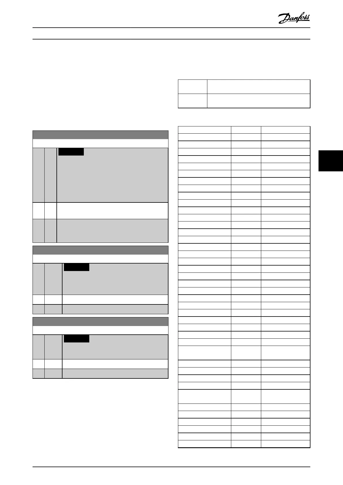
6.1.1 5-1* Digital Inputs
The digital inputs are used for selecting various functions
in the frequency converter. All digital inputs can be set to
the functions listed in Table 6.1.
Functions in group 1 have higher priority than functions in
group 2.
Group 1 Reset, coast stop, reset, and coast stop, quick stop,
DC brake, Stop, and the [O] key.
Group 2 Start, pulse start, reversing, start reversing, jog,
and freeze output.
Table 6.1 Function Groups
Digital input function Select Terminal
No operation [0] All, terminal 32, 33
Reset [1] All
Coast inverse [2] All, terminal 27
Coast and reset inverse [3] All
Quick stop inverse [4] All
DC brake inverse [5] All
Stop inverse [6] All
Start [8] All, terminal 18
Latched start [9] All
Reversing [10] All, terminal 19
Start reversing [11] All
Enable start forward [12] All
Enable start reverse [13] All
Jog [14] All, terminal 29
Preset reference on [15] All
Preset ref bit 0 [16] All
Preset ref bit 1 [17] All
Preset ref bit 2 [18] All
Freeze reference [19] All
Freeze output [20] All
Speed up [21] All
Speed down [22] All
Set-up select bit 0 [23] All
Set-up select bit 1 [24] All
Precise stop inverse [26] 18, 19
Precise start, stop [27] 18, 19
Catch up [28] All
Slow down [29] All
Counter input [30] 29, 33
Pulse input edge
triggered
[31] 29, 33
Pulse input time based [32] 29, 33
Ramp bit 0 [34] All
Ramp bit 1 [35] All
Latched precise start [40] 18, 19
Latched precise stop
inverse
[41] 18, 19
External interlock [51] –
DigiPot increase [55] All
DigiPot decrease [56] All
DigiPot clear [57] All
DigiPot hoist [58] All
Counter A (up) [60] 29, 33
Programming Design Guide
MG80C502 Danfoss A/S © 10/2016 All rights reserved. 47
6
6