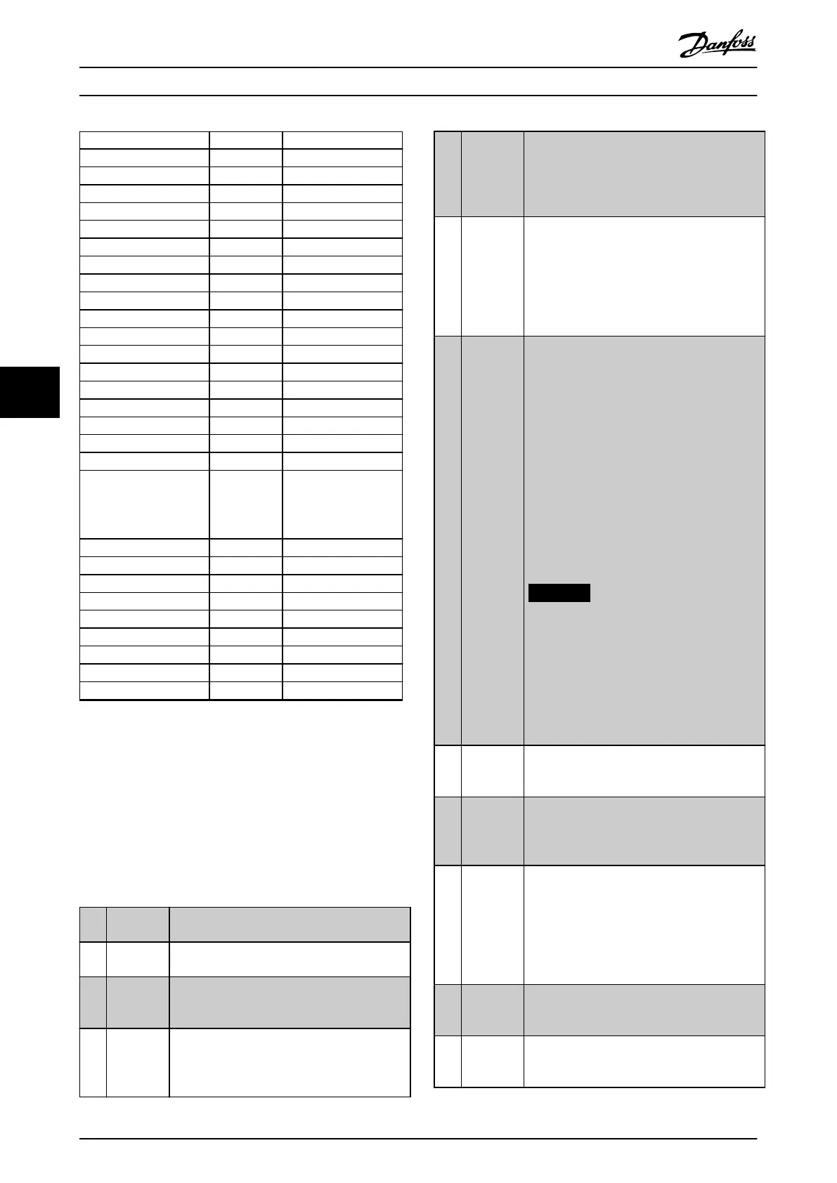
Digital input function Select Terminal
Counter A (down) [61] 29, 33
Reset Counter A [62] All
Counter B (up) [63] 29, 33
Counter B (down) [64] 29, 33
Reset counter B [65] All
Mech. brake feedb. [70] All
Mech. brake feedb. inv. [71] All
PID error inv. [72] All
PID reset I-part [73] All
PID enable [74] All
MCO specic [75] –
PTC card 1 [80] All
PROFIdrive OFF2 [91] –
PROFIdrive OFF3 [92] –
Light-load detection [94] All
Mains Loss [96] 32, 33
Mains loss inverse [97] 32, 33
Start edge triggered [98] –
Safety option reset [100] Resets the safety
option. Available only
when the safety option
is mounted.
Start homing [110] All
Activate touch [111] All
Relative position [112] All
Enable reference [113] All
Sync. to position mode [114] All
Home sensor [115] 18, 32, 33
Home sensor inverse [116] 18, 32, 33
Touch sensor [117] 18, 32, 33
Touch sensor inverse [118] 18, 32, 33
Table 6.2 Digital Input Function
VLT
®
AutomationDrive FC 301/FC 302 standard terminals
are 18, 19, 27, 29, 32, and 33. Terminal 29 functions as an
output only in FC 302.
Functions dedicated to only 1 digital input are stated in
the associated parameter.
All digital inputs can be programmed to these functions:
[0] No
operation
No reaction to signals transmitted to the
terminal.
[1] Reset Resets frequency converter after a trip/alarm.
Not all alarms can be reset.
[2] Coast
inverse
(Default digital input 27): Coast stop, inverted
input (NC). The frequency converter leaves the
motor in free mode. Logic 0⇒coast stop.
[3] Coast and
reset
inverse
Reset and coast stop inverted input (NC).
Leaves motor in free mode and resets
frequency converter. Logic 0⇒coast stop and
reset.
[4] Quick stop
inverse
Inverted input (NC). Generates a stop in
accordance with quick stop ramp time set in
parameter 3-81 Quick Stop Ramp Time. When
the motor stops, the shaft is in free mode.
Logic 0⇒quick stop.
[5] DC brake
inverse
Inverted input for DC brake (NC). Stops motor
by energizing it with a DC current for a certain
time period. See parameter 2-01 DC Brake
Current to parameter 2-03 DC Brake Cut In Speed
[RPM]. The function is only active when the
value in parameter 2-02 DC Braking Time is
dierent from 0. Logic 0⇒DC brake.
[6] Stop
inverse
Stop inverted function. Generates a stop
function when the selected terminal goes from
logical level 1 to logical level 0.
The stop is performed according to the
selected ramp time:
•
Parameter 3-42 Ramp 1 Ramp Down
Time,
•
Parameter 3-52 Ramp 2 Ramp Down
Time,
•
Parameter 3-62 Ramp 3 Ramp down
Time, and
•
Parameter 3-72 Ramp 4 Ramp Down
Time.
NOTICE
When the frequency converter is at the
torque limit and has received a stop
command, it may not stop by itself. To
ensure that the frequency converter
stops, congure a digital output to [27]
Torque limit and stop. Connect this digital
output to a digital input that is
congured as coast.
[8] Start (Default digital input 18): Select start for a
start/stop command. Logic 1 = start,
logic 0 = stop.
[9] Latched
start
If a pulse is applied for minimum 2 ms, the
motor starts. The motor stops when stop
inverse is activated, or a reset command (via
DI) is given.
[10] Reversing (Default digital input 19). Change the direction
of motor shaft rotation. Select logic 1 to
reverse. The reversing signal only changes the
direction of rotation. It does not activate the
start function. Select both directions in
parameter 4-10 Motor Speed Direction. The
function is not active in process closed loop.
[11] Start
reversing
Used for start/stop and for reversing on the
same wire. Signals on start are not allowed at
the same time.
[12] Enable
start
forward
Disengages the counterclockwise movement
and allows clockwise direction.
Programming
VLT
®
Advanced Harmonic Filter AHF 005/AHF 010
48 Danfoss A/S © 10/2016 All rights reserved. MG80C502
6
6