1 Introduction
1.1 Purpose of the Design Guide
This design guide introduces important aspects of the VLT
®
Advanced Harmonic Filters AHF 005/AHF 010 (referred to
as AHF) for VLT
®
FC Series frequency converters. It
describes harmonics and how to mitigate them, and it
provides installation instructions and guidance on how to
program the frequency converter.
The technical data and information on the connection
conditions are on the nameplate and in the documen-
tation. Always observe the recommendations and
instructions in this document.
Danfoss technical literature is also available online at
drives.danfoss.com/knowledge-center/technical-documen-
tation/.
1.2 Intended Use
The lters are components designed for installation in
electrical systems or machinery.
When installing in machines, commissioning of the lters
(that is starting of operation as directed) is prohibited until
it is proven that the machine complies with the Machinery
Directive 2006/42/EC. Observe EN 60204.
The VLT
®
Advanced Harmonic Filter AHF 005/AHF 010 is
intended for use with:
•
VLT
®
HVAC Drive FC 102.
•
VLT
®
Refrigeration Drive FC 103.
•
VLT
®
AQUA Drive FC 202.
•
VLT
®
AutomationDrive FC 301/FC 302.
1.3
Organization of the Design Guide
Chapter 1 Introduction: The general purpose of the design
guide and compliance with international directives.
Chapter 2 Introduction to Harmonics and Mitigation: An
introduction to harmonics and how to mitigate them.
Chapter 3 Basic Operating Principle of the AHF: A description
of the operating principles of harmonic
lters.
Chapter 4 Requirements for Installation: Basic requirements
for mechanical and electrical installation.
Chapter 5 Selection of Advanced Harmonic Filter: Information
on how to calculate the correct lter size, ordering
numbers, and accessories.
Chapter 6 Programming: Describes the necessary parameter
settings for lter operation.
Chapter 7 Specications: A compilation of technical data in
table and graphics format.
Chapter 8 Spare Parts: Overview of all available spare parts,
including ordering numbers.
Chapter 9 Appendix: A compilation of power loss tables.
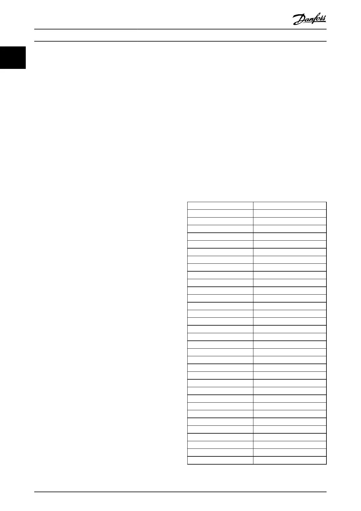
1.4 Abbreviations, Symbols, and
Conventions
1.4.1 Abbreviations
°C
Degrees Celsius
°F
Degrees Fahrenheit
A Ampere/AMP
AC Alternating current
AHF Advanced Harmonic Filter
AWG American wire gauge
CDM Complete drive module
DC Direct current
DPF Displacement power factor
EMC Electromagnetic compatibility
f
M,N
Nominal motor frequency
FC Frequency converter
g Ground gravity
HCS Harmonic calculation software
I
M,N
Nominal motor current
I
INV
Rated inverter output current
Hz Hertz
kHz Kilohertz
kVAr Kilo-volt-ampere reactive
LCP Local control panel
m Meter
mA Milliampere
MCT Motion control tool
mH Millihenry inductance
min Minute
ms Millisecond
nF Nanofarad
Nm Newton meters
P Active power
PCC Point of common coupling
PDS Power drive system
PELV Protective extra low voltage
PF Power factor
P
M,N
Nominal motor power
Introduction
VLT
®
Advanced Harmonic Filter AHF 005/AHF 010
4 Danfoss A/S © 10/2016 All rights reserved. MG80C502
11