4.2 Electrical Installation
4.2.1 Terminals - Short Overview
The VLT
®
Advanced Harmonic Filter AHF 005/AHF 010
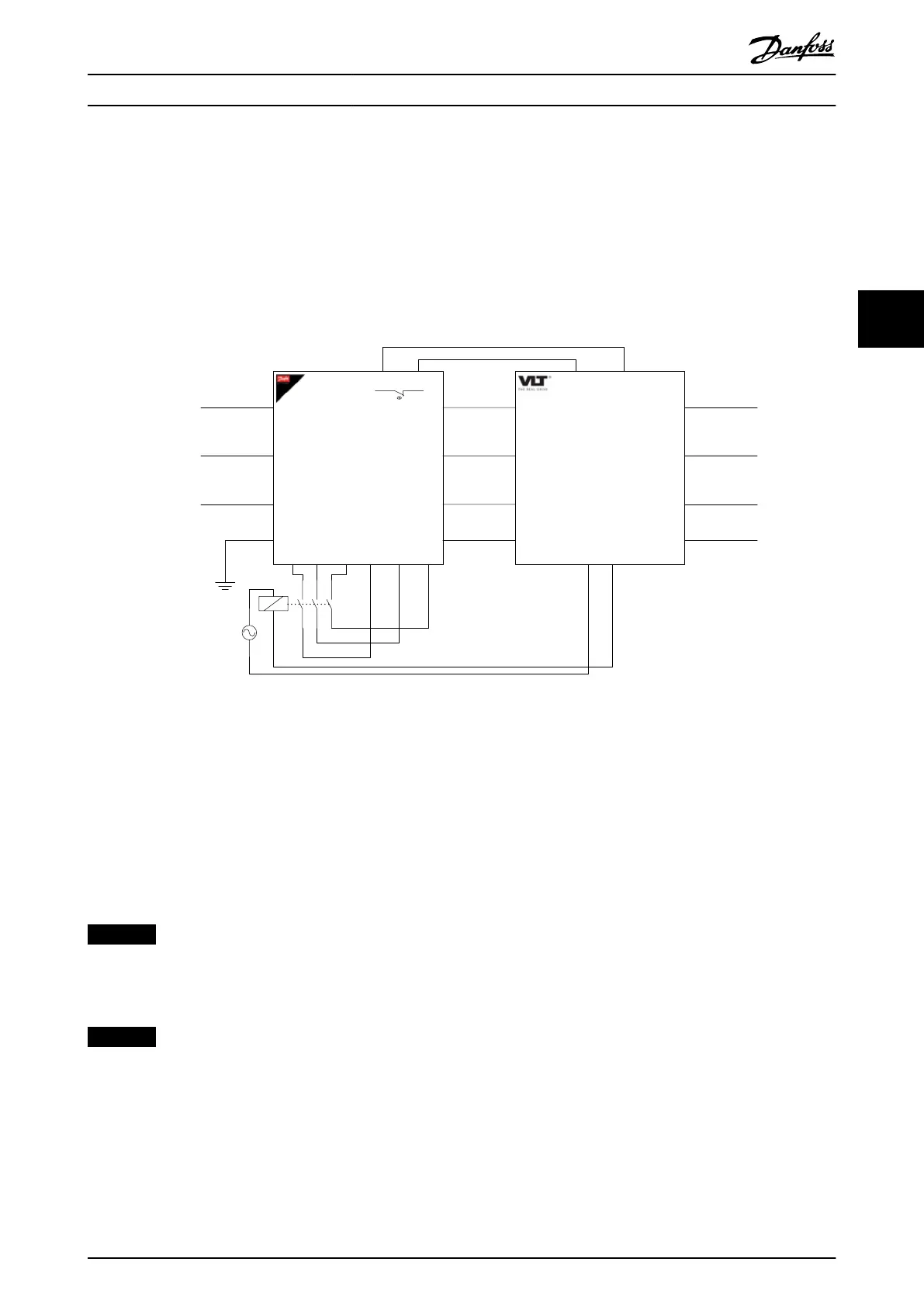
contains the following terminals:
•
X1.1–X1.3 are the mains terminals.
•
X2.1–X2.3 are the output terminals to the
frequency converter.
•
X3.1–X4.3 are optional connection terminals for
capacitor disconnect.
•
A and B are the temperature switch connected to
the frequency converter.
•
PE for protective earth.
X3.1 X3.2 X3.3 X4.1 X4.2 X4.3
X1.1
X1.2
X1.3
X2.1
X2.2
X2.3
A B
91 (L1 96 (U)
97 (V)
98 (W)
92 (L2)
93 (L3)
95 (PE)
PE
01 02
Relay
24V DC
24 - 240V AC
depending on
contactor type
Capacitor
disconnect
(optional)
12
(24 V)
27
(coast inverse)
99 (PE)
AHF
VLT
Frequency
converter
Mains
supply
Motor
PE
130BB904.10
Illustration 4.13 Connection Diagram
4.2.1.1 Terminals for Capacitor Disconnect
From the factory, the terminals for the capacitor disconnect
are bypassed or looped with jumpers. When using an
external contactor, remove the jumper and use a relay.
Refer to chapter 5.2.2 Capacitor Disconnect Contactors,
chapter 5.3.1.2 IP21/NEMA 1 Upgrade Kit with Built-in
Capacitor Disconnect Circuitry, and Illustration 5.6 for more
details.
NOTICE
A Danfoss frequency converter can be used for
controlling the relay of an external contactor. See
chapter 6 Programming for more information.
NOTICE
The capacitor disconnect feature does not apply to VLT
®
AutomationDrive FC 301.
The power factor of the VLT
®
Advanced Harmonic Filter
AHF 005/AHF 010 decreases with decreasing load. At no
load, the power factor is 0, and the capacitors produce
leading current of approximately 25% of the rated lter
current. In applications where this reactive current is not
acceptable, disconnect the capacitor bank via terminals
X3.1, X3.2, X3.3, and X4.1, X4, X4.3.
Per default (on delivery) the wiring shortens terminal X3.1
with X4.1, X3.2 with X4.2, and X3.3 with X.4.3. If no
capacitor disconnect is required, do not change these
shortened terminals.
If a disconnection of the capacitors is required, place a 3-
phase contactor between terminals X3 and X4. Using AC3
contactors is recommended, see chapter 5.2.2 Capacitor
Disconnect Contactors. An IP21/NEMA 1 upgrade kit with
built-in capacitor disconnect circuitry is available as an
option, see chapter 5.3.1 IP21/NEMA 1 Upgrade Kit.
Paralleling AHF
It is possible to run 2 lters in parallel and still use both
the capacitor disconnect and the temperature switch. Wire
according to Illustration 4.14.
Requirements for Installati... Design Guide
MG80C502 Danfoss A/S © 10/2016 All rights reserved. 27
4 4