1.80
1.60
1.40
1.20
1.00
0.80
0.60
0.40
0.20
0.00
0 10 20 30 40 50 60 70 80 90 100
n [%]
1 100% load
2 50% load
3 25% load
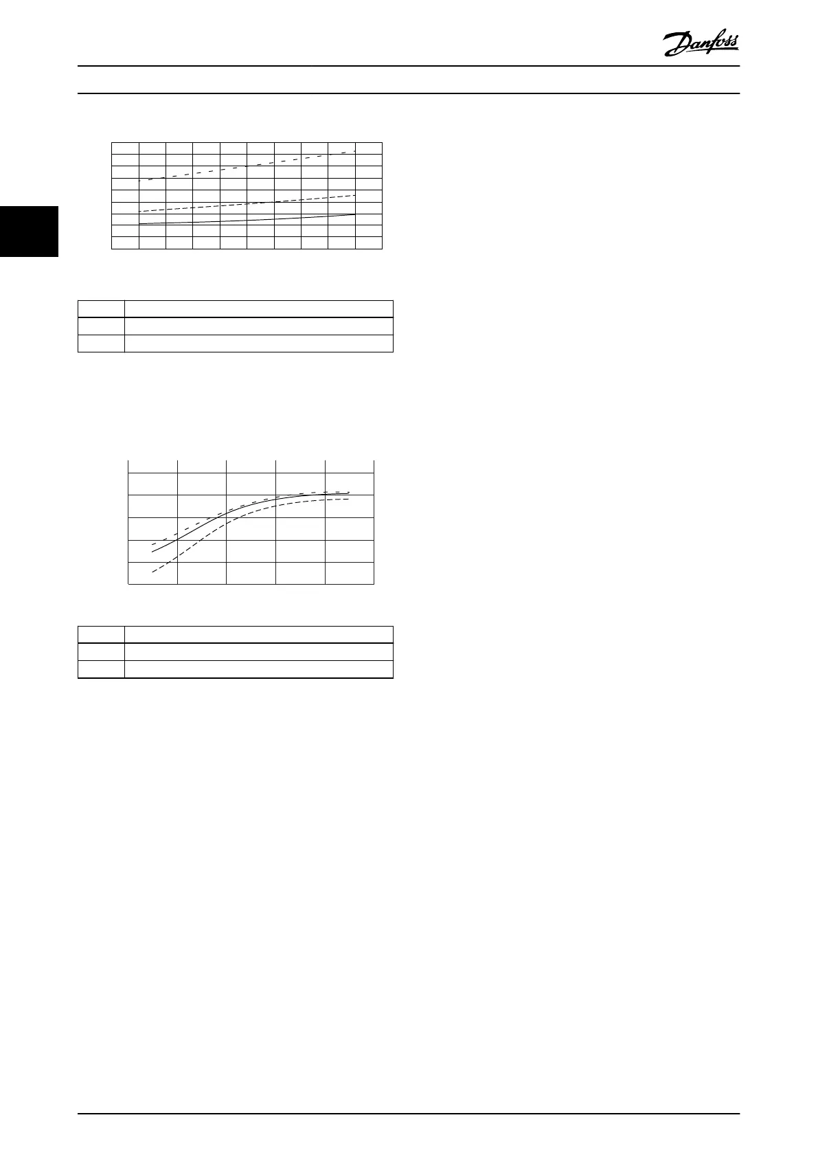
Illustration 3.11 Frequency converter power loss data.
CDM relative losses (P
L, CDM
) [%] versus speed
(n) [% of nominal speed].
130BD931.11
n [%]
0 20 40 60 80 100
100.00
98.00
96.00
94.00
92.00
90.00
η
CDM (freq,load)
[%]
1
2
3
1 100% load
2 50% load
3 25% load
Illustration 3.12 Frequency converter eciency data.
CDM eciency (η
CDM(freq, load)
) [%] versus speed
(n) [% of nominal speed].
Interpolation of power loss
Determine the power loss at an arbitrary operating point
using 2-dimensional interpolation.
3.2.4 Losses and Eciency of a Motor
The eciency of a motor running at 50–100% of the
nominal motor speed and at 75–100% of the nominal
torque is practically constant. This is valid both when the
frequency converter controls the motor, or when the motor
runs directly on mains.
The eciency depends on the type of motor and the level
of magnetization.
For more information about motor types, refer to the
motor technology brochure at www.vlt-drives.danfoss.com.
3.2.5 Losses and Eciency of a Power Drive
System
To estimate the power losses at dierent operating points
for a power drive system, sum the power losses at the
operating point for each system component:
•
Frequency converter.
•
Motor.
•
Auxiliary equipment.
3.2.6 Losses and Eciency of a Power Drive
System with Installed Filter
The power loss of the VLT
®
Advanced Harmonic Filter
AHF005/AHF010 is specied in 5 dierent operating points
as 0–100% load. The current load and power loss are
specied in each operating point. See Table 9.2 for power
losses.
The power loss in the AHF depends on the operating point
and is a function of the input current in the AHF. The
identication point of operation of the AHF is based on
the input current to the frequency converter. The input
current of the frequency converter equals the input current
to the AHF.
I
In,AHF
=I
In,VLT
The output current of the frequency converter consists of
the torque-producing component and the motor magneti-
zation component. Dierent factors aect the relationship
between the input current and output current of a
frequency converter. For example, part load causes a
signicant dierence between the 2 currents.
I
In,VLT
≠I
out,VLT
Calculate the input current of the frequency converter with
this formula:
I
In,VLT
=I
out,VLT
x cos(phi) x f
motor
[%] x load
motor
[%] x 1.02
•
I
out,VLT
: Nominal output current from the
frequency converter. Find the data in the
frequency converter design guide or VLT
®
ecoSmart.
•
Cos (phi): Motor power factor. Find the data on
the motor nameplate. Alternatively, use a
reference value from EN 50598, see Table 3.2.
•
f
motor
[%]: Percentage value of the nominal
operating frequency in the motor in the range 0–
1.
•
load
motor
[%]: Percentage value of the torque-
producing component or torque-producing
current in the motor in the range 0–1. The value
is typically from the design of the application.
Basic Operating Principle o...
VLT
®
Advanced Harmonic Filter AHF 005/AHF 010
18 Danfoss A/S © 10/2016 All rights reserved. MG80C502
33