User is defined as: integrator, operator, servicing,
maintenance staff.
Standards
Use of safe stop on terminal 37 requires that the user satisfies
all provisions for safety including relevant laws, regulations
and guidelines. The optional safe stop function complies
with the following standards.
EN 954-1: 1996 Category 3
IEC 60204-1: 2005 category 0 – uncontrolled stop
IEC 61508: 1998 SIL2
IEC 61800-5-2: 2007 – safe torque off (STO) function
IEC 62061: 2005 SIL CL2
ISO 13849-1: 2006 Category 3 PL d
ISO 14118: 2000 (EN 1037) – prevention of
unexpected start up
The information and instructions of the instruction manual
are not sufficient for a proper and safe use of the safe stop
functionality. The related information and instructions of the
relevant Design Guide must be followed.
Protective Measures
•
Safety engineering systems may only be installed
and commissioned by qualified and skilled
personnel
•
The unit must be installed in an IP54 cabinet or in
an equivalent environment
•
The cable between terminal 37 and the external
safety device must be short circuit protected
according to ISO 13849-2 table D.4
•
If any external forces influence the motor axis (e.g.
suspended loads), additional measures (e.g., a
safety holding brake) are required in order to
eliminate hazards
Safe Stop Installation and Set-Up
WARNING
SAFE STOP FUNCTION!
The safe stop function does NOT isolate mains voltage to the
frequency converter or auxiliary circuits. Perform work on
electrical parts of the frequency converter or the motor only
after isolating the mains voltage supply and waiting the
length of time specified under Safety in this manual. Failure
to isolate the mains voltage supply from the unit and waiting
the time specified could result in death or serious injury.
•
It is not recommended to stop the frequency
converter by using the Safe Torque Off function. If
a running frequency converter is stopped by using
the function, the unit will trip and stop by coasting.
If this is not acceptable, e.g. causes danger, the
frequency converter and machinery must be
stopped using the appropriate stopping mode
before using this function. Depending on the
application a mechanical brake may be required.
•
Concerning synchronous and permanent magnet
motor frequency converters in case of a multiple
IGBT power semiconductor failure: In spite of the
activation of the Safe torque off function, the
frequency converter system can produce an
alignment torque which maximally rotates the
motor shaft by 180/p degrees. p denotes the pole
pair number.
•
This function is suitable for performing mechanical
work on the frequency converter system or
affected area of a machine only. It does not provide
electrical safety. This function should not be used
as a control for starting and/or stopping the
frequency converter.
The following requirements have to be meet to perform a
safe installation of the frequency converter:
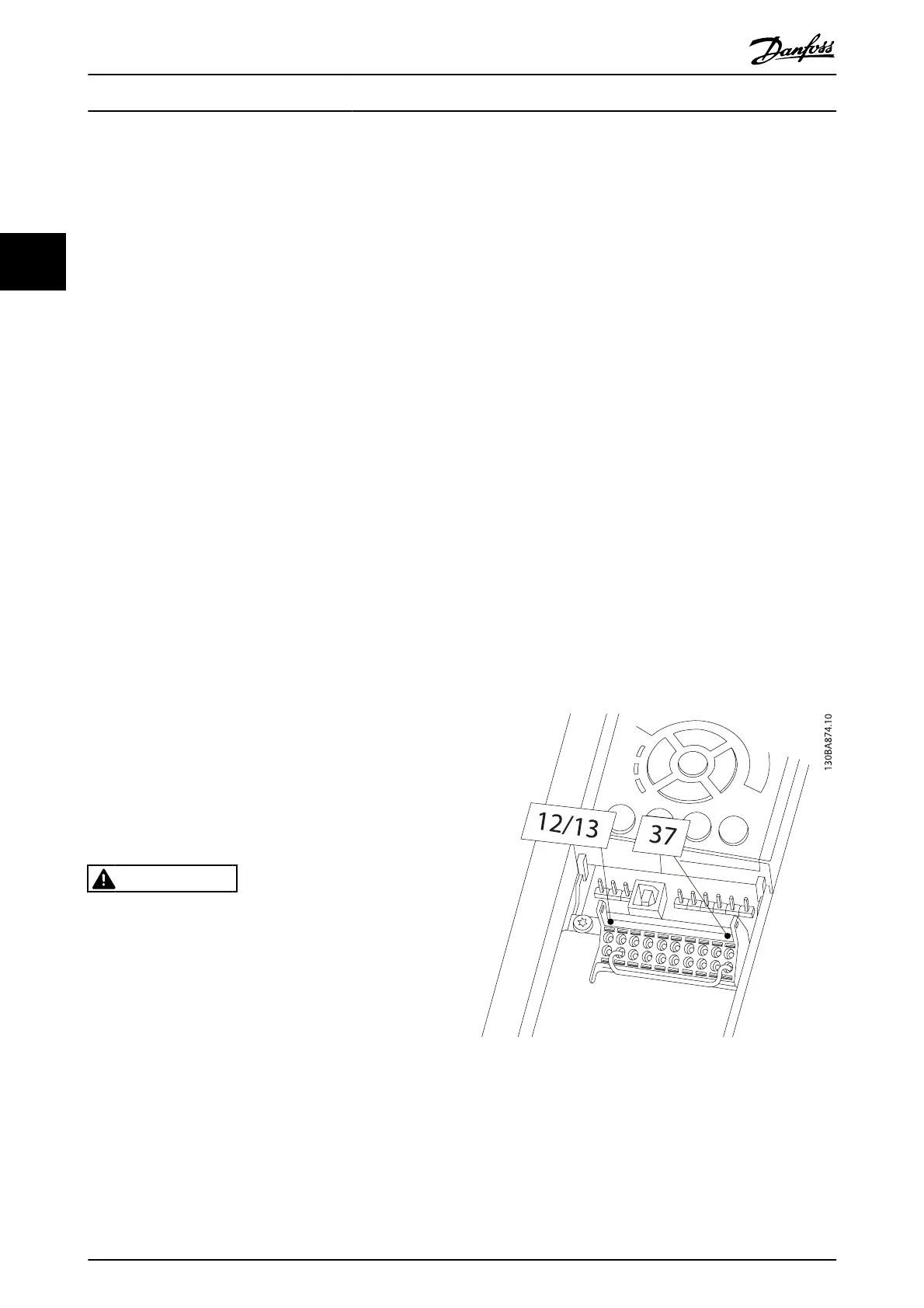
1. Remove the jumper wire between control
terminals 37 and 12 or 13. Cutting or breaking the
jumper is not sufficient to avoid short-circuiting.
(See jumper on Illustration 2.15.)
2. Connect an external Safety monitoring relay via a
NO safety function (the instruction for the safety
device must be followed) to terminal 37 (safe stop)
and either terminal 12 or 13 (24V DC). The Safety
monitoring relay must comply with Category 3 (EN
954-1) / PL “d” (ISO 13849-1).
Illustration 2.15 Jumper between Terminal 12/13 (24V) and 37
Installation
VLT
®
AutomationDrive Operating
Instructions
18 MG.33.AJ.02 - VLT
®
is a registered Danfoss trademark
2
 Loading...


