EasyManuals Logo

Danfoss VLT AutomationDrive User Manual

Danfoss VLT AutomationDrive
89 pages
To Next Page IconTo Next Page
To Previous Page IconTo Previous Page
Page #21 background imageLoading...
Page #21 background image
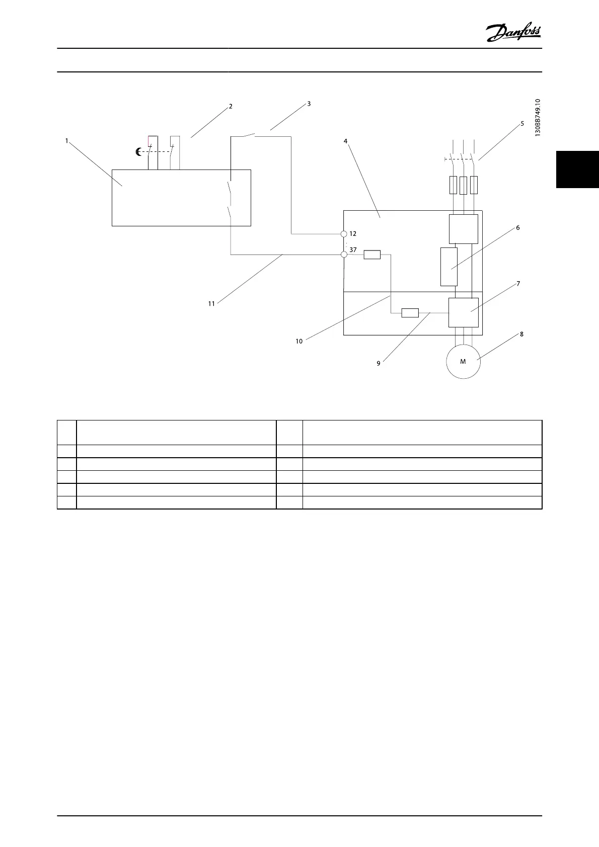
Illustration 2.16 Installation to Achieve a Stopping Category 0 (EN 60204-1) with Safety Cat. 3 (EN 954-1) / PL “d” (ISO 13849-1).
1 Safety device Cat. 3 (circuit interrupt device, possibly with
release input)
7Inverter
2 Door contact 8 Motor
3 Contactor (Coast) 9 5V DC
4 Frequency converter 10 Safe channel
5 Mains 11 Short-circuit protected cable (if not inside installation cabinet)
6Control board
Safe Stop Commissioning Test
After installation and before first operation, perform a commissioning test of the installation making use of safe stop. Moreover,
perform the test after each modification of the installation.
Installation
VLT
®
AutomationDrive Operating
Instructions
MG.33.AJ.02 - VLT
®
is a registered Danfoss trademark 19
2
2

Table of Contents

Other manuals for Danfoss VLT AutomationDrive

Questions and Answers:

Question and Answer IconNeed help?

Do you have a question about the Danfoss VLT AutomationDrive and is the answer not in the manual?

Danfoss VLT AutomationDrive Specifications

General IconGeneral
Supply Voltage3 x 200-240 V ±10% 3 x 380-500 V ±10% 3 x 525-600 V ±10%
EnclosureIP20
Output Power Range0.25 kW - 1.5 MW
Communication ProtocolsModbus RTU
Protection FeaturesOvercurrent, Overvoltage, Undervoltage, Short circuit, Ground fault, Motor overload
Ambient Temperature Range-10°C to +50°C (14°F to 122°F)

Related product manuals