EasyManuals Logo

Danfoss VLT FC 100 Design Guide

Danfoss VLT FC 100
281 pages
To Next Page IconTo Next Page
To Previous Page IconTo Previous Page
Page #175 background imageLoading...
Page #175 background image
130BB019.10
1
2
3
4
5
6
7
8
9
10
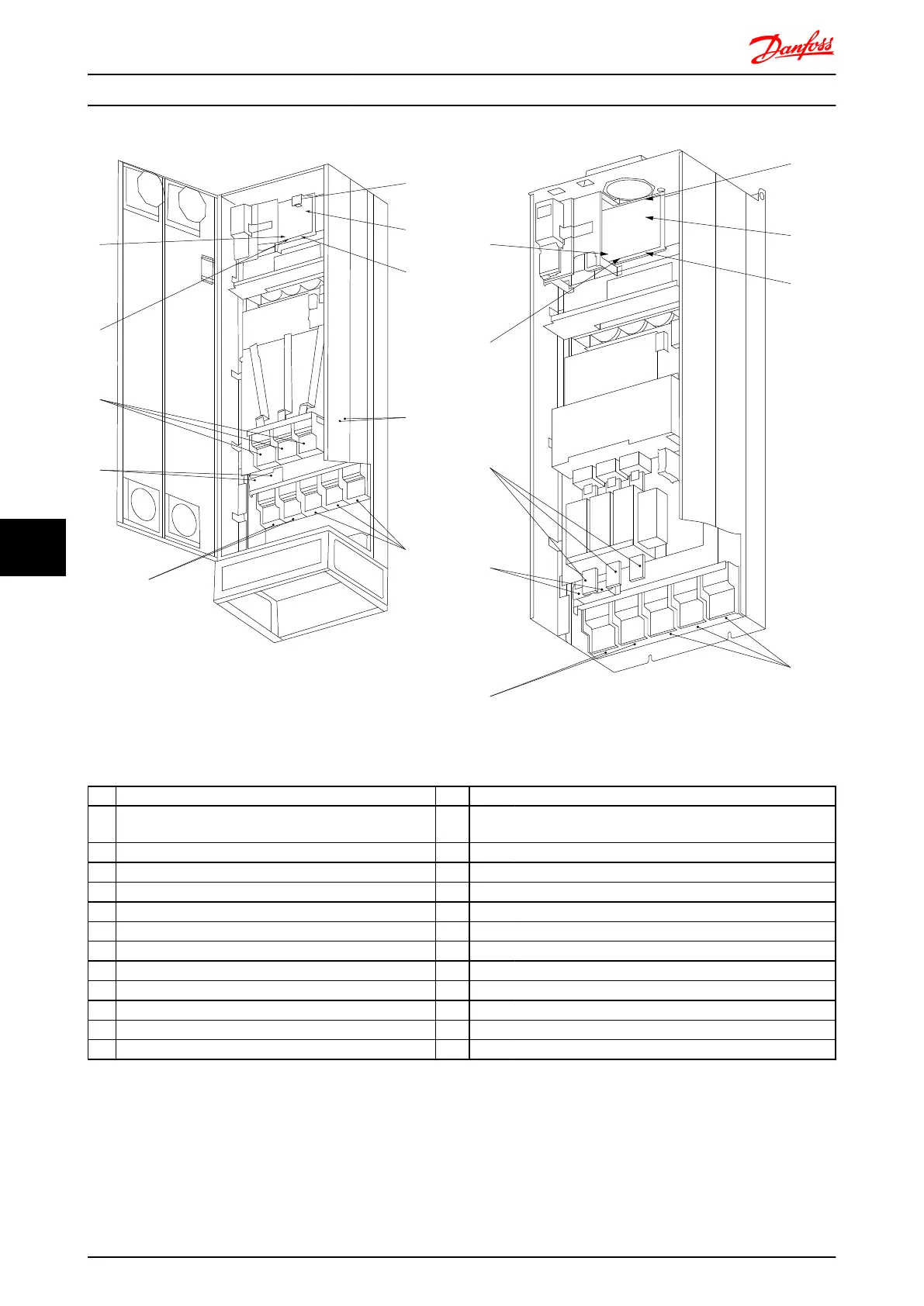
Illustration 8.36 Compact IP 21 (NEMA 1) and IP 54 (NEMA 12)
frame size E1
130BB020.10
1
2
3
4
5
6
7
8
10
Illustration 8.37 Compact IP 00 (Chassis) with disconnect, fuse
and RFI filter, frame size E2
1)
AUX Relay 5) Load sharing
01 02 03 -DC +DC
04 05 06 88 89
2) Temp Switch 6) SMPS Fuse (see fuse tables for part number)
106 104 105 7) Fan Fuse (see fuse tables for part number)
3) Line 8) AUX Fan
R S T 100 101 102 103
91 92 93 L1 L2 L1 L2
L1 L2 L3 9) Mains ground
4) Brake 10) Motor
-R +R U V W
81 82 96 97 98
T1 T2 T3
Electrical Installation FC 300 Design Guide
174 MG.33.BD.02 - VLT
®
is a registered Danfoss trademark
88

Table of Contents

Other manuals for Danfoss VLT FC 100

Questions and Answers:

Question and Answer IconNeed help?

Do you have a question about the Danfoss VLT FC 100 and is the answer not in the manual?

Danfoss VLT FC 100 Specifications

General IconGeneral
BrandDanfoss
ModelVLT FC 100
CategoryDC Drives
LanguageEnglish

Related product manuals