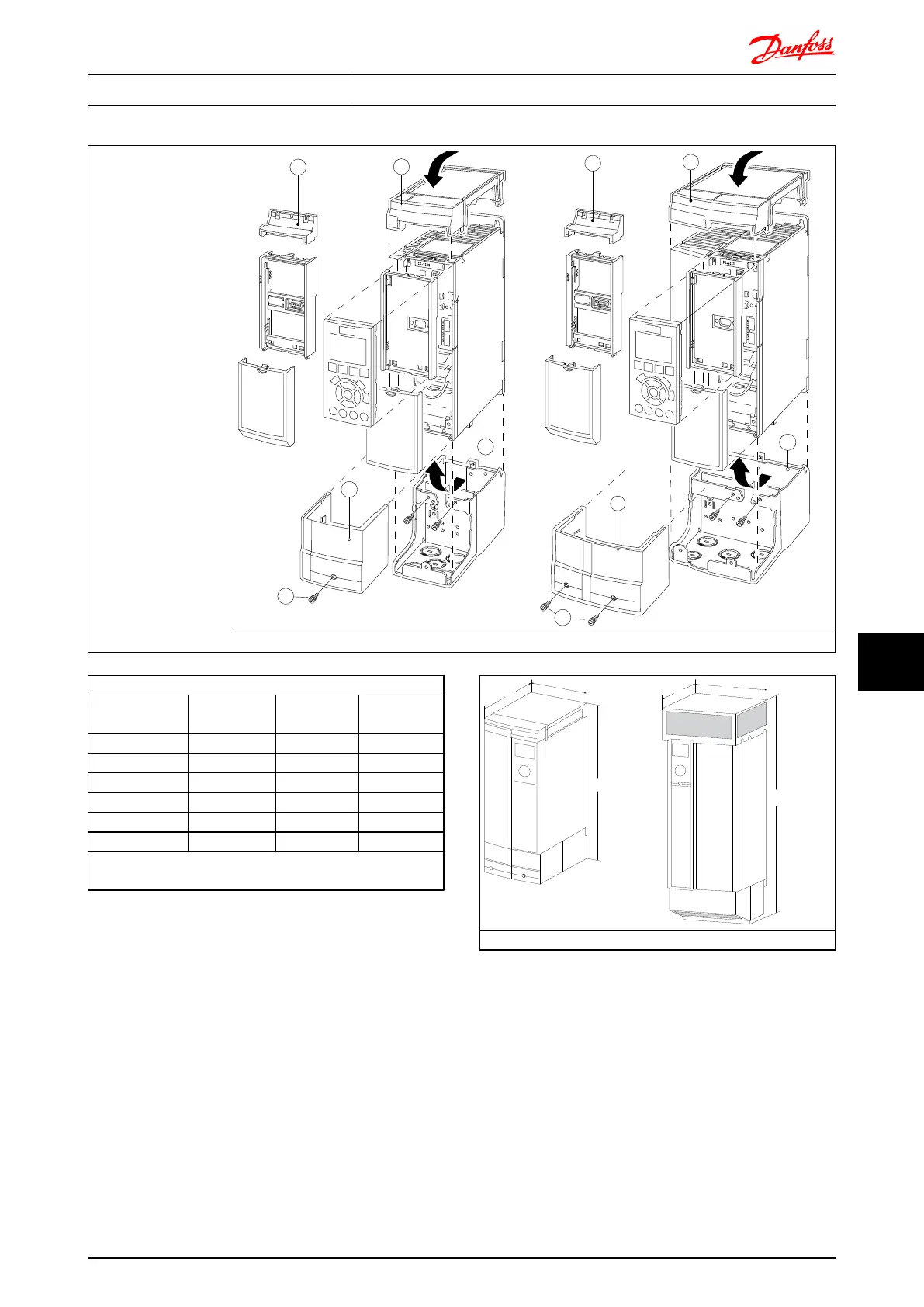
A – Top cover
B – Brim
C – Base part
D – Base cover
E – Screw(s)
Place the top cover as
shown. If an A or B
option is used the brim
must be fitted to cover
the top inlet. Place the
base part C at the
bottom of the drive and
use the clamps from the
accessory bag to correctly
fasten the cables. Holes
for cable glands:
Size A2: 2x M25 and
3xM32
Size A3: 3xM25 and
3xM32
A2 Enclosure A3 Enclosure
Dimensions
Enclosure type
Height (mm)
A
Width (mm)
B
Depth (mm)
C*
A2 372 90 205
A3 372 130 205
B3 475 165 249
B4 670 255 246
C3 755 329 337
C4 950 391 337
* If option A/B is used, the depth will increase (see section
Mechanical Dimensions for details)
A2, A3, B3 B4, C3, C4
Options and Accessories FC 300 Design Guide
MG.33.BD.02 - VLT
®
is a registered Danfoss trademark 249
10
10
 Loading...


