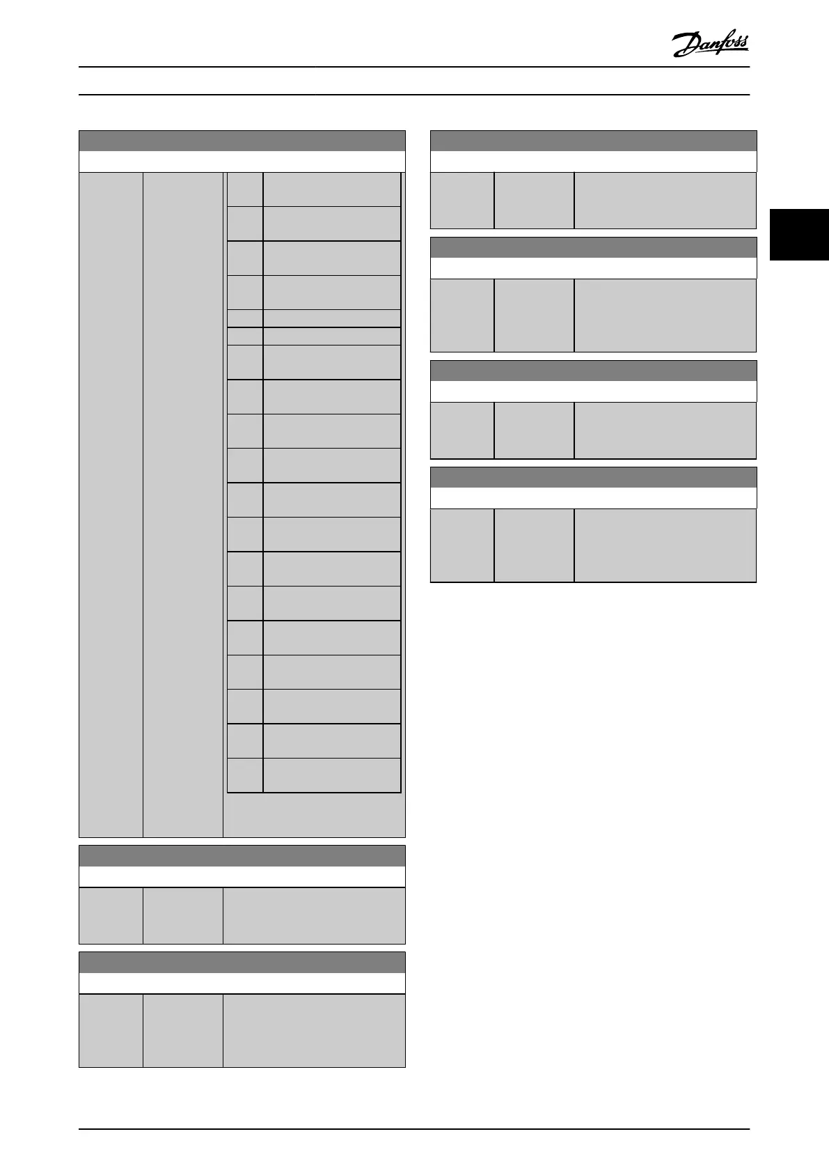
5-90 Digital & Relay Bus Control
Range: Function:
Bit 0 CC digital output, terminal
27
Bit 1 CC digital output, terminal
29
Bit 2 GPIO digital output,
terminal X 30/6
Bit 3 GPIO digital output,
terminal X 30/7
Bit 4 CC relay 1 output terminal
Bit 5 CC relay 2 output terminal
Bit 6 Option B relay 1 output
terminal
Bit 7 Option B relay 2 output
terminal
Bit 8 Option B relay 3 output
terminal
Bit 9–
15
Reserved for future
terminals
Bit 16 Option C relay 1 output
terminal
Bit 17 Option C relay 2 output
terminal
Bit 18 Option C relay 3 output
terminal
Bit 19 Option C relay 4 output
terminal
Bit 20 Option C relay 5 output
terminal
Bit 21 Option C relay 6 output
terminal
Bit 22 Option C relay 7 output
terminal
Bit 23 Option C relay 8 output
terminal
Bit
24–31
Reserved for future
terminals
Table 3.16 Digital Output Bits
5-93 Pulse Out #27 Bus Control
Range: Function:
0 %* [0 - 100 %] Contains the frequency to apply to
the digital output terminal 27 when
it is congured as bus-controlled.
5-94 Pulse Out #27 Timeout Preset
Range: Function:
0 %* [0 - 100 %] Contains the frequency to apply to
the digital output terminal 27 when
it is congured as bus-controlled
timeout, and timeout is detected.
5-95 Pulse Out #29 Bus Control
Range: Function:
0 %* [0 - 100 %] Contains the frequency to apply to
the digital output terminal 29 when
it is congured as bus-controlled.
5-96 Pulse Out #29 Timeout Preset
Range: Function:
0 %* [0 - 100 %] Contains the frequency to apply to
the digital output terminal 29 when
it is congured as bus-controlled
timeout, and timeout is detected.
5-97 Pulse Out #X30/6 Bus Control
Range: Function:
0 %* [0 - 100 %] Contains the frequency to apply to
the digital output terminal 6 when
it is congured as bus-controlled.
5-98 Pulse Out #X30/6 Timeout Preset
Range: Function:
0 %* [0 - 100 %] Contains the frequency to apply to
the digital output terminal 6 when
it is congured as bus-controlled
timeout, and timeout is detected.
Parameter Descriptions Programming Guide
M0010001 Danfoss A/S © 10/2019 All rights reserved. 105
3 3
 Loading...


